


Hardware components | ||||||
 |
| × | 1 | |||
| × | 1 | ||||
| × | 1 | ||||
Software apps and online services | ||||||
 |
| |||||
| ||||||
| ||||||
In many situations, we only want a car to be able to complete some specific tasks in a new scenario. In traditional self-driving tasks, a new walking or patrolling task is generally required to be coordinated by LIDAR, camera and other devices. Such solution requires tuning the parameters for each new environment and is not flexible enough. To be able to make the car adapt to new scenarios quickly, we got inspiration from Learning from Demonstrations. We perform imitation learning with flexible and easy-to-collect visual data and neural networks. With such approach, we only need to manually drive the car to collect image data as well as driving parameters as labels to build the dataset and train the network model. At application, the car reads the camera and then outputs the steering angle through the model to complete the task.
Here's what the final result looks like:
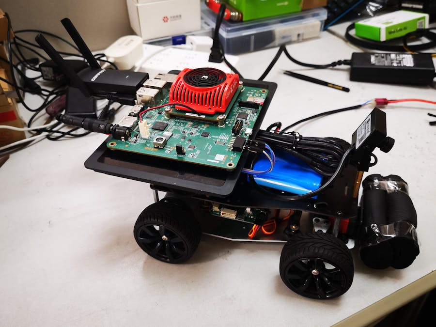
Just to clarify: You may notice the car shown in later pictures has a LiDAR mounted. Our model car happens to come with a LiDAR and it's unrelated to this project. We later removed it when shooting the final demonstration video.
Prerequisite: familiarity with Linux, a deep-learning framework of your choice and ROS (Robotic Operating System)
All the code used in this project can be found in the code section or this bitbucket repo.
Part 1: Collect the Training DataThe model car we used was originally equipped with a FriendlyElec NanoPC-T4 SBC, so we collected the dataset with that and trained the network before equipping the car with a KV260 board. You can skip to part 3 and setup KV260 with ROS first if your car doesn't come with a SBC.
We are using a supervised learning approach. And the most important part of it is a labeled dataset.
For this project, we'll drive the car manually, record the image collected by the camera in 640x480 resolution and label them with the steering angle input from us.
Step 1: prepare the ROS workspace
We assume that ROS is already installed on the SBC controlling the car. You can follow part 3 in this tutorial to create a KV260 image with ROS or follow the installation guide on wiki.ros.org if you are using a different SBC for this step.
Connect to the car via SSH and create our workspace:
mkdir -p ~/ros_ws/srcThe ROS driver for our car accepts standard AckermannDriveStamped message as the control input. In this part, we need three nodes: car driver, a keyboard controlling node and a USB camera node.
Copy the car driver to ros_ws/src via scp or other tools you familiar with, and download the other two by executing the following command on the SBC:
cd ~/ros_ws/src
# download the ackermann-drive-teleop project:
git clone https://github.com/gkouros/ackermann-drive-teleop ackermann_drive_teleop
# install the usb_cam from ROS with apt. Skip the following two commands if you are using KV260.
sudo apt update
sudo apt install ros-noetic-usb-cam
Now build the workspace:
source /opt/ros/noetic/setup.bash
cd ~/ros_ws
catkin_make
Step 2: drive the car and record some data
We first used a black carpet with white lane drawn on it as an example scene for proof of concept:
That's where the pictures in this tutorial comes from. We later drived the car around in our lab to gather a different dataset for the final result in our cover video.
In ROS, all nodes communicate with each other using messages. ROS comes with a utility called rosbag which can record all the messages sent by nodes in a timely order, and we'll use that for this step.
Open four ssh sessions to the car for various nodes.
First node is the car driver:
cd ~/ros_ws
source ./devel/setup.bash
# the exact package and node name in the command below depends on the actual car used
# consult your car manual for the actual command.
roslaunch base_control base_control.launch
The second one is for USB camera:
cd ~/ros_ws
source ./devel/setup.bash
# This launch file comes with the official ROS package and is conveniently configured to capture 640x480 on /dev/video0. We'll just use this one.
roslaunch usb_cam usb_cam-test.launch
The third one is for recording a rosbag:
cd ~/ros_ws
source ./devel/setup.bash
rosbag record
Launch the keyboard control node in the final one:
cd ~/ros_ws
source ./devel/setup.bash
rosrun ackermann_drive_teleop keyop.py
Now you can control your car with the arrow keys on the 4th terminal. Put your car on the field and drive it around on the desired path:
After that, terminate the rosbag command with Ctrl+C and you'll find a {date}-{time}.bag file in ~/ros_ws. Copy this file back to your linux desktop and shutdown the car.
Step 3: extract the images and labels
Now let's go back to our Linux PC and extract our dataset. We'll be labelling each image with the last recorded steering angle using a python script.
Open a terminal and create a ros workspace:
source /opt/ros/noetic/setup.bash
mkdir -p ~/ros_ws/src
cd ~/ros_ws/src
# create our package
catkin_create_pkg data_extractor std_msgs ackermann_msgs cv_bridge rospy
cd data_extractor
mkdir scripts
Create ~/ros_ws/src/data_extractor/scripts/extractor.py with the source code provided in the code section and add executable permission to it:
chmod +x extractor.pyBuild the workspace:
source /opt/ros/noetic/setup.bash
cd ~/ros_ws
catkin_make
source ./devel/setup.bash
Copy the previously recorded rosbag to ~/ros_ws and extract our images:
mkdir dataset
# replace {date}-{time}.bag with the filename of your rosbag
rosrun data_extractor extractor.py labels.csv {date}-{time}.bag dataset
The dataset folder contains the extracted image and the corresponding labels are stored in labels.csv. We'll use these to train our neural network in the next part.
Part 2: Build and Train Our NetworkIn this part, we'll build our neural network steering the car. As a demonstration, we'll be using PyTorch to build a simple CNN for the lane carpet scene. You can pick any deep-learning framework supported by Vitis-AI and follow the corresponding Tutorial from Xilinx to create your quantized model.
My team mate later traind a ResNet18 for the lab scene in the cover video, but the procedure is the same so we won't duplicate it here.
Step 1: prepare the Vitis-AI docker environment
We'll use Vitis-AI 2.0 in this tutorial. Let's first download the source code:
git clone --recurse-submodules https://github.com/Xilinx/Vitis-AI
cd Vitis-AI
git checkout v2.0
You can only use CPU for training but it'll be faster if a NVIDIA GPU is used instead.
Unfortunately the GPU docker is too big and Xilinx doesn't provide a prebuilt image for us. We need to build it following the README.md in Vitis-AI repository:
cd setup/docker
./docker_build_gpu.sh
Step 2: code and train our network
The network used in this part is based on the PyTorch CIFAR10 Tutorial and the custom dataset is created following PyTorch Data Loading Tutorial. I highly recommend you to read through both tutorials to understand what's going on in the code provided.
There are three scripts used in this step:
- dataset.py: the utility to load our dataset.
- model_reg.py: the neural network we used.
- train.py: the training script
Copy these created files and the dataset into the Vitis-AI directory and enter our container:
cd Vitis-AI
./docker_run.sh xilinx/vitis-ai-gpu:latest
We'll be greeted with the banner below:
Activate the PyTorch envionment as shown in the picture, and execute our training script:
conda activate vitis-ai-pytorch
python3 training/train_reg.py
After the 'Finished Training' output, we'll get the trained network state dictionary file named state_dict_rgb.pth.
Step 3: Quantizing the network
Vitis-AI runs AI inference with int8 while our neural network is trained with float point. We need to convert the model using tools from Xilinx Vitis-AI docker container. It first converts the model, then determines various model parameters with supplied input data and save the result for Vitis-AI compiler.
The script for quantizing the model is provided as quantize_xlnx.py. It's written based on the Xilinx example.
Call the script to get the quantized model:
python3 training/quantize_xlnx.py calib
python3 training/quantize_xlnx.py testWe now have the quantized model in quantize_result/Net_int.xmodel. The exact file name will be different depending on the deep-learning framework you choose. This model needs to be compiled for the specific DPU we deploy on KV260. We'll do this after we obtain the arch.json describing our DPU.
Part 3: Setup KV260In this part, we'll be building a custom PL bitstream with Vivado and Xilinx provided tcl scripts, as well as a PetaLinux image with all the software packages we need in later steps.
Step 1: create the base hardware platform
Our model car is controlled over UART, so I need to wire a UART to the pmod interface on the KV260. Xilinx has a tutorial on building a custom hardware design: Using Vivado to Build the Hardware Design. I'll just list the exact customization I made, instead of describing the whole process.
At the time of writing, the kv260-vitis repository is only suitable for Vivado 2021.1. To use Vivado 2021.2, we need to change the board name for KV260 SOM and carrier board. We need to rename "*:kv260:*" to "*:kv260_som:*" and change "xilinx.com:som240:som240_1_connector:1.0" to "xilinx.com:kv260_carrier:som240_1_connector:1.2".
You can change it manually after cloning the kv260-vitis repository, or you can apply the provided patch on top of release-2021.1 branch.
Generate an Extensible XSA using these commands:
source {your_vitis_install_dir}/Vitis/2021.2/settings64.sh
cd platforms/vivado/kv260_ispMipiRx_vcu_DP
make xsa
Now let's open the project in Vivado. First, open the Vivado GUI, then run the following command from the Vivado tcl console:
open_project ./project/kv260_ispMipiRx_vcu_DP.xprHere's a part where the Xilinx tutorial doesn't mention: we need to disable incremental synthesis, otherwise Vitis will complain about missing files when building the overlay later.
In the Flow Navigator panel on the left-hand side, click Settings under Project Manager. In the pop-up window, click Synthesis under Project Settings:
Click the three dot on the right of Incremental synthesis and choose Disable incremental synthesis:
Click OK to close the settings window. Under IP integrator, click on Open Block Design. An IP integrator block design becomes visible that contains the Processing System (PS) IP and other PL IPs.
Double click the ZynqMP in the center of the block diagram:
Click the UART0 as shown in the picture above. You'll be broght to the screen below:
Check the UART0 box and select EMIO in the IO field. Then click OK. You'll notice there's a new UART_0 in the ZynqMP block:
Right click on that and select Make external. I also decided to rename the external connection to uart_ps0 here. While at it, I removed the PL I2C and connected the PS I2C0 for the onboard camera, added a second PL uart for future use and incoporated this awesome temperature-controlled fan. Here's my final block diagram:
Now click Run Synthesis to complete the synthesis and click Open Elaborated design:
Click the '19 I/O ports' shown in picture and you'll find a port list below the main window:
tomverbeure on GitHub organized a package pin list here: kv260_pinout.py. We can find the pins we need and assign the ports to it, as shown in the picture above.
Now our hardware platform is ready. Click "Generate Bitstream" in the Flow Navigator and complete the steps, then click Export Platform to get our new.xsa file.
Step 2: build the overlay
First, let's replace overlays/dpu_ip in kv260-vitis with dsa/DPU-TRD/dpu_ip from Vitis-AI repository to use the latest DPU.
Then, follow the Xilinx tutorial to Create a Vitis Platform and Integrate the overlay into the Platform. I'll use OpenCV for image preprocessing later so I built overlays/examples/benchmark to incoporate a larger DPU in PL. After building, you'll find arch.json, dpu.xclbin and kv260_ispMipiRx_vcu_DP_wrapper.bit in overlays/examples/benchmark/binary_container_1/sd_card/
Step 3: write a device tree for our overlay
Since I'm using the smartcam base platform, I can modify the kv260-smartcam.dtsi for our use. Enable uart0, add the PL uart we wrote before and move the I2C definition from the PL node into the PS i2c0. You can find vai20-2uart.dtsi in the provided source code.
Step 4: Build PetaLinux
First, download PetaLinux 2021.1 and the K26 Starter Kit BSP from Xilinx download page.
Install petalinux and create our base project:
source {your_petalinux_install}/PetaLinux/2021.1/settings.sh
# update petalinux for kv260
petalinux-upgrade -u http://petalinux.xilinx.com/sswreleases/rel-v2021/sdkupdate/2021.1_update1/ -p "aarch64" --wget-args "--wait 1 -nH --cut-dirs=4"
petalinux-create -t project -s /<path to>/xilinx-k26-starterkit-v2021.1-final.bsp -n xilinx-k26-starterkit-2021.1
cd xilinx-k26-starterkit-2021.1
# import our xsa from step 1
petalinux-config --get-hw-description /path/to/xsa
# build it first. This will take a while to finish:
petalinux-build
# set board variant for KV260
echo 'BOARD_VARIANT = "kv"' >>  project-spec/meta-user/conf/petalinuxbsp.conf
Create a package for our overlay using files from step 2 and 3 following Add New FPGA Firmware:
# I've renamed the files from previous steps to vai20-2uart.* here.
petalinux-create -t apps --template fpgamanager -n user-firmware --enable --srcuri "vai20-2uart.bit vai20-2uart.dtsi vai20-2uart.xclbin shell.json"
Add ROS into our image following ROS 2 in Kria kv260 with Petalinux 2021.2. In Step 2 of this tutorial,, instead of adding ROS 2 Rolling, we add ROS Noetic, which means adding the following layers:
${PROOT}/project-spec/meta-ros/meta-ros-backports-hardknott
${PROOT}/project-spec/meta-ros/meta-ros-common
${PROOT}/project-spec/meta-ros/meta-ros2
${PROOT}/project-spec/meta-ros/meta-ros2-rolling
And in step 3 we create project-spec/meta-user/recipes-core/images/petalinux-image-minimal.bbappend with the following content:
inherit ros_distro_${ROS_DISTRO}
inherit ${ROS_DISTRO_TYPE}_image
To make other ROS packages available for selection, we add the packages we need into project-spec/meta-user/conf/user-rootfsconfig:
CONFIG_ros-core
CONFIG_usb-cam
CONFIG_ackermann-msgs
CONFIG_cv-bridge
CONFIG_cv-bridge-dev
CONFIG_catkin-dev
CONFIG_ackermann-msgs-dev
CONFIG_sensor-msgs-dev
CONFIG_roscpp-dev
CONFIG_vai20-2uart
CONFIG_tf2
CONFIG_tf2-dev
Add Vitis-AI 2.0 libraries following How to use recipes-vitis-ai.
After that, open petalinux rootfs config:
petalinux-config -c rootfsselect the packages we need in user packages menu:
We'll be building the ROS packages on the KV260 board, so we need to select all the -dev packages and packagegroup-petalinux-self-hosted from Petalinux Package Groups menu.
Finally, let's build our images:
# compile everything
petalinux-build
# package BOOT.BIN. Add --force if you've previously generated it.
petalinux-package --boot --u-boot --dtb images/linux/u-boot.dtb
# package the sdcard image
petalinux-package --wic --bootfiles "ramdisk.cpio.gz.u-boot boot.scr Image system.dtb"
Step 5: Flash the images
Write the generated petalinux image to the sd card and power on the board. After that, upgrade the BOOT.BIN following Boot Firmware Updates.
We now have our KV260 board ready. Install it on the model car and continue following the next part of the tutorial.
Part 4: Deploy the modelIn this part, we'll finally get KV260 to steer the model car.
Step 1: compile the network
Copy the arch.json from part 3 and Net_int.xmodel from part 2 to the Vitis-AI directory and enter the Vitis-AI Docker container:
cd Vitis-AI
./docker_run.sh xilinx/vitis-ai-gpu:latest
conda activate vitis-ai-pytorch
Run the following command to compile the network:
vai_c_xir -x /PATH/TO/quantized.xmodel -a /PATH/TO/arch.json -o /OUTPUTPATH -n netnameThe output file are in the specified output path as shown in the picture above.
Step 2: write the deloyment code
If you haven't done it, prepare a ROS workspace on KV260 as demonstrated in the step 1 of part 1.
Create our package for the deployment code:
cd ~/ros_ws/src
source ./devel/setup.bash
# create our package
catkin_create_pkg lane_dl_xlnx std_msgs ackermann_msgs cv_bridge roscpp
cd lane_dl_xlnx
mkdir launch model
And now it's the time for more code. We'll be running the model using the VART API. You can find the Xilinx sample code for using VART API from resnet50.cpp in Vitis-AI repository.
lane_dl_xlnx.cpp is our code for using VART API with ROS. Save it as ~/ros_ws/src/lane_dl_xlnx/src/main.cpp.
To build our code, we need to add it to the CMakeLists.txt in the package. The finished script is provided in the source code.
We also need a launch file to start the node. Save lane_dl_xlnx.launch as ~/ros_ws/src/lane_dl_xlnx/src/.Copy the compiled model from step 1 to ~/ros_ws/src/lane_dl_xlnx/model/lane.xmodel and build our workspace:
cd ~/ros_ws
catkin_make
Here comes the most exciting part. Put your car in the previously trained scene and connect two ssh sessions.
In the first session, load the PL bitstream and start the neural network node:
# unload the default firmware
sudo xmutil unloadapp
# load the firmware we created
sudo xmutil loadapp vai20-2uart
# start the node
cd ~/ros_ws
source ./devel/setup.bash
roslaunch lane_dl_xlnx lane_dl_xlnx.launch
Start the car driver in the second session:
cd ~/ros_ws
source ./devel/setup.bash
# the exact package and node name in the command below depends on the actual car used
# consult your car manual for the actual command.
roslaunch base_control base_control.launch1
The car should be following our previous driving path on itself!
ResultHere's our car running on the lane carpet:
And you can try some different scenes and neural networks like what we've done in the cover video.


Comments
Please log in or sign up to comment.