This circuit came about during some experiments I was doing in relation to building a transistor tester. Identifying the pins of a transistor using an Arduino involves altering the output pin directions and taking voltage measurements. This set me wondering, what would happen if I connected up a 2 lead bi-colored LED (with resistor) and alternated the output pin directions. I hoped the LED would alternately flash both of its colors, I was not disappointed.
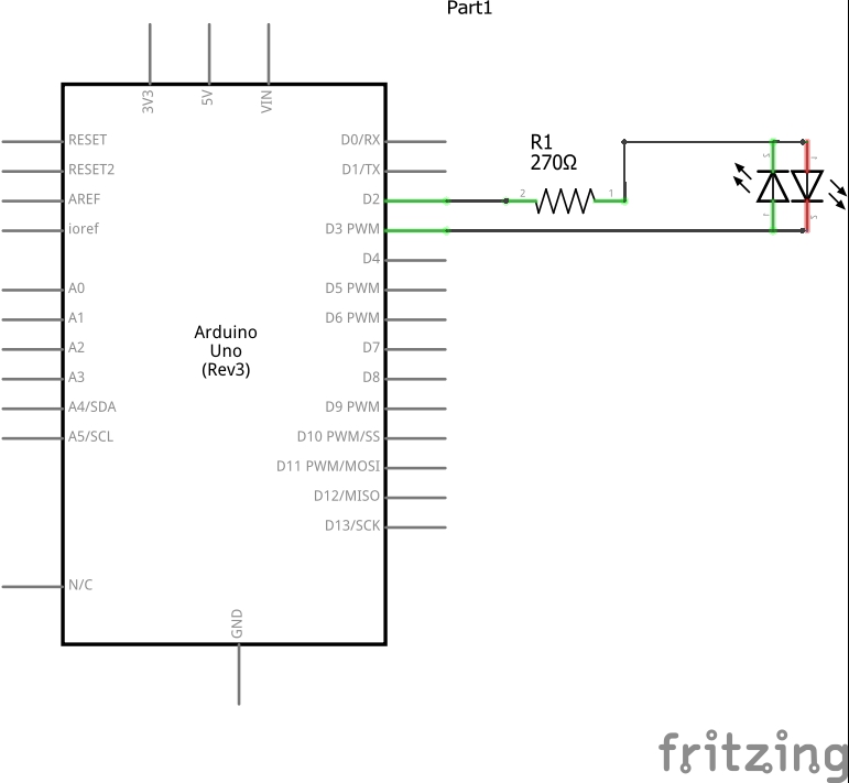
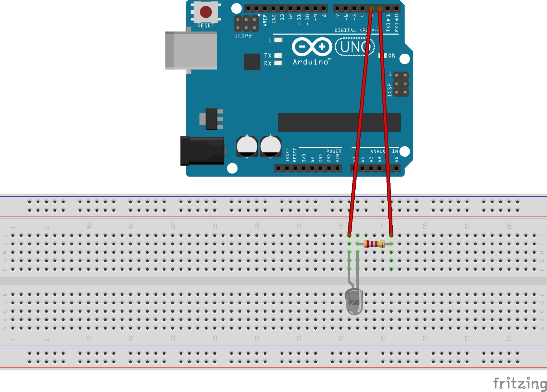
Circuit description:The circuit comprises of an Arduino (UNO) a 2 wire bi-colored LED and a 270 ohm resistor.
The resistor value used is somewhat arbitrary, I had salvaged the LED I used so I first connected it to 5 volts via a 1k resistor and measured the voltages across it (2v green, 1.6v red).
Using the standard formula (supply voltage-LED voltage drop)/current, with current set to 20 milliamps (pretty standard for LED's), gives resistor values of 150 and 170 ohms respectively for the recorded voltages.
The nearest value in my tub of components was the 270 ohm so re-arranging the formula to (supply voltage-LED voltage drop)/resistance (270 ohm) shows we have LED operating currents of 10 and 12 mA for 2 and 1.6 volts respectively, in my view this gives sufficient brightness.
Software description:The code for this project is very simple:
In the code setup section:
We assign the 2 pins we are using as output.
In the code loop section:
We call the function which sets the output pin voltages for the led.
We delay 2 seconds.
We call our function again this time with the pin identifiers reversed.
We delay 2 seconds.
At this point we go back to the start of our loop.
The function first sets both output pins to 0 volts, this is important as you don't want both pins pushing 5 volts into each other, and then sets one pin to 5 volts before exiting.


_ztBMuBhMHo.jpg?auto=compress%2Cformat&w=48&h=48&fit=fill&bg=ffffff)


Comments
Please log in or sign up to comment.