


Hardware components | ||||||
_ztBMuBhMHo.jpg?auto=compress%2Cformat&w=48&h=48&fit=fill&bg=ffffff) |
| × | 1 | |||
 |
| × | 1 | |||
| × | 1 | ||||
| × | 1 | ||||
 |
| × | 1 | |||
 |
| × | 1 | |||
Software apps and online services | ||||||
 |
| |||||
Hand tools and fabrication machines | ||||||
 |
| |||||
Here's how to use this to program your own ATtiny chips! It covers both through-hole (DIP) and surface-mount (SOIC) chips: bit.ly/attduino
I've been using ATtiny85 chips with Arduino code in projects for many years now, thanks to Arjun Ganesan's brilliant tutorial. Now that I'm building my own PCBs, I need to program a lot more chips to power them! My old "permanent install with breadboard wires inside a Tupperware" solution just doesn't cut it anymore.
So, I wanted to create a beautiful, functional PCB, to program other beautiful, functional PCBs!
As mentioned above, I borrowed Arjun's tutorial that I've been using to program ATtiny chips with Arduino code. This is a great way to do it, because there are a bajillion tutorials out there for Arduino, and these chips are cheap and easy to get. There are a few incompatibilities (like the Tone library) – but workarounds exist, and the chip has 5 GPIOs, including PWM, in a small space. They truly are tiny!
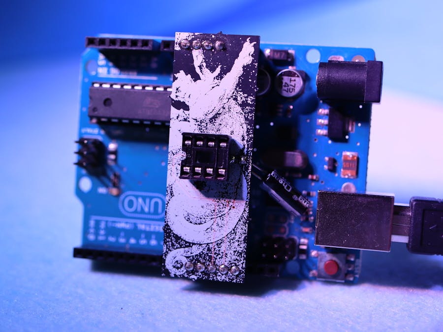
The PCBThis circuit makes for a nice tiny shield, since it uses a bunch of adjacent pins on the Arduino Uno. That means it can be quite narrow – just be sure to plug it into the correct pins! For future versions, I think it might help to have those labeled on top.
I followed this tutorial, by Brian Benchoff, to create the ATtiny85 part in KiCad: https://hackaday.com/2016/11/17/creating-a-pcb-in-everything-kicad-part-1
The capacitor and 8-pin DIP socket are a bit crowded, but I get around that by mounting them on opposite sides of the board.
For programming surface-mount chips, I instead soldered on male headers. These connect to the IC test/programming clip I got from SparkFun, via female jumper wires.
I'd been digging around on OldBookIllustrations.com and found this wonderful public-domain image from Dante's Inferno, featuring Virgil and Dante riding on the back of Geryon, an underworld creature.
The fine lines got a bit blown out – I think I was pushing the resolution guidelines for silkscreen... I think I'd like to rework this one anyway, but for future projects, I've been told that solder mask tends to have higher accuracy than silkscreen anyway, so maybe I could give that a go.
I used Photoshop to turn that into a high-res halftone image, and then KiCad's "Bitmap to Component Converter" to turn the halftone image into a silkscreen footprint (so OSH Park would print it in white, on top of the purple solder mask or black PCB). Much of the process was the same used by Andrew Sowa in this tutorial. This process will be the subject of another Hackster project soon. :)
For the back, I used one of the many "mandala" symmetrical-drawing apps for iPad to create a symmetrical rendering of the word "ATtiny" (with some creative capitalization):
I'm already thinking about other, more beautiful and personal designs (outside the rectangle), but it does the job for now!
The proofIt works!! I've been using this to program ATtiny85 chips while prototyping my PCB badge for Avnet's 100-year anniversary.

Comments
Please log in or sign up to comment.