The day is hot and sunny in San Francisco, and Ben has kicked me out of the office.
I've just spent about an hour building this little jig, and to my wonder and delight, IT WORKS!!!! (On the first try!)
I highly recommend using one of these, for several reasons:
Here's the story:I spent a couple of hack nights with my friends Jono and Rhodey, trying different methods of programming the popular little ESP8266 boards.
Rhodey and I tried programming it with an Uno; this worked from his Linux machine, but not from my Mac – although I could find the board's IP once it was programmed. The issues persisted when I tried different methods at home later. We used a mashup of this tutorial from ElectroDragon, this Instructable, and rancidbacon's walkthrough (which says that using an Uno is "not very legit": hack at your own discretion).
Jono and I programmed it directly using an FTDI cable; that went much better, and I was finally able to upload the WifiWebServer sketch! He showed me the jig he'd built, which is something I hadn't gotten around to yet. So, today, smitten with envy, I completed mine – in my own style. I.e.: it looks like it shouldn't work, but somehow it does...
Make has an awesome how-to for programming these using an FTDI cable. Fortunately, my FTDI cable—yanked from a Seeed Grove kit—is at 3V3 by default! This means that I didn't have to worry about scaling down from 5V so as to not to fry the ESP.
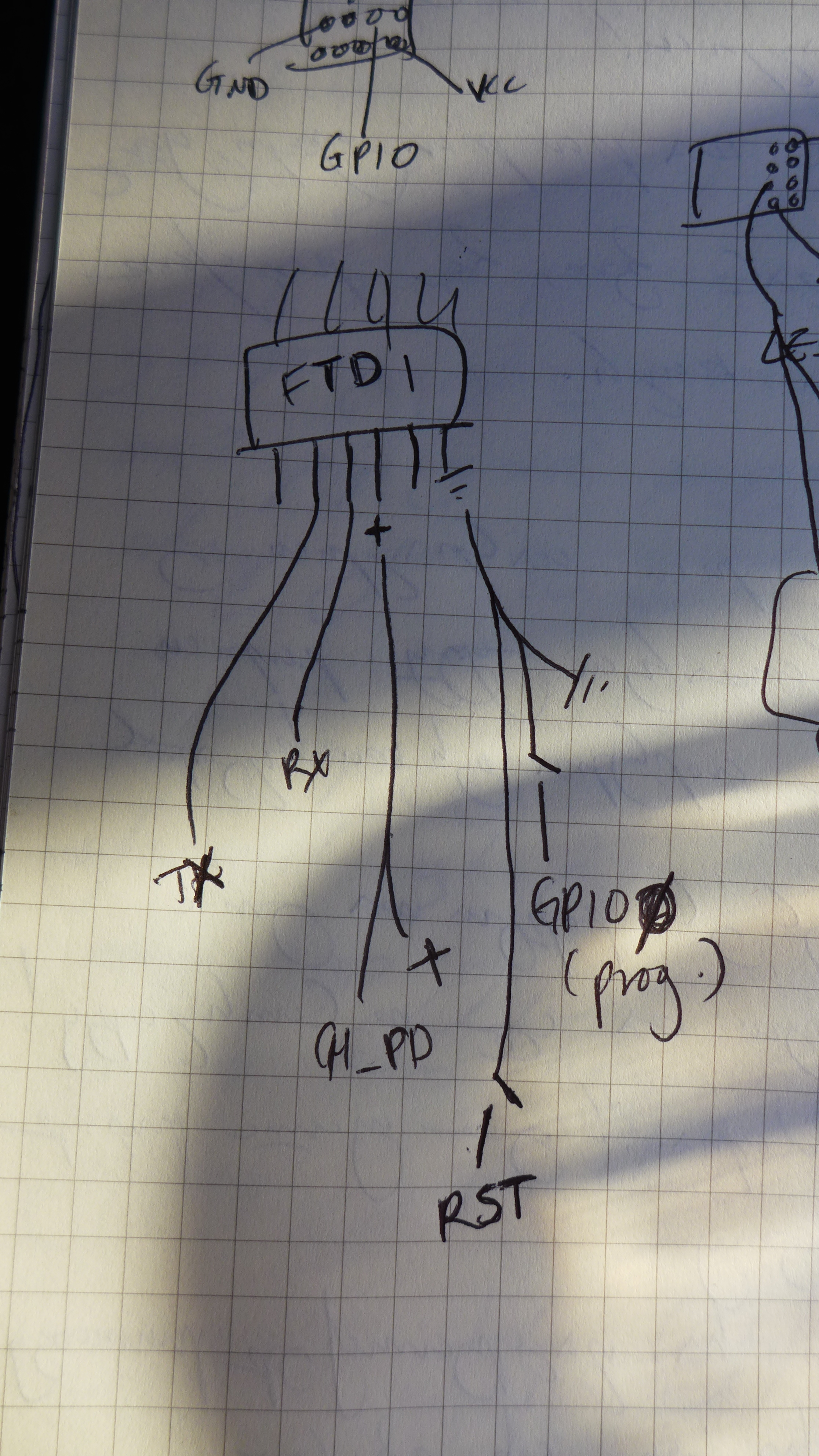
Following the diagram given in the above article...
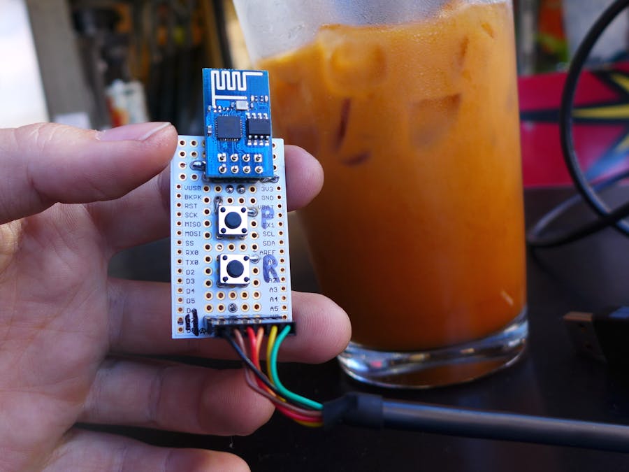
...I took a protoboard and stuck a row of male-male headers at one end, so I could plug the FTDI cable into it directly. The row of proto-pins is only 5 wide, but as you can see, you can just leave off the DTR pin so there's no problem. I marked the GND end, to stay oriented.
At the other end of the board, I put a two rows of 4 male-male headers, where I'd stick the ESP8266. It's a great friction fit – the board goes on without much trouble, and it comes off easily too, but is firmly held with good contact to all the necessary pins.
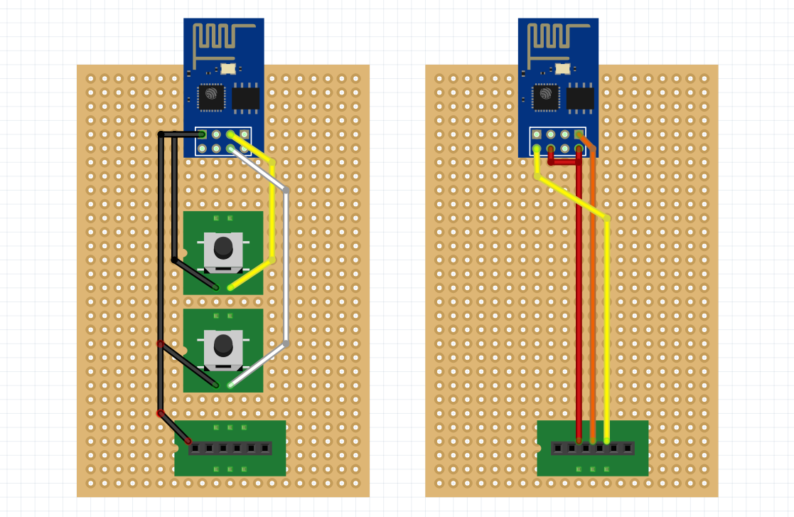
Now, there are a couple of things to consider when wiring this up. See that GND-GPIO0 connection? It's the black wire that connects two pins to the GND wire of the FTDI programmer.
GPIO0 needs to be connected to GND in order to program the board. However, during normal use, it must be disconnected. And I always forget to unplug it. So, I put in a button (P) for that connection.
The other button (R) pulls the RST reset pin low, connecting it to GND.
That's the general logic of it. Next, I think I'll put in a wire for the GPIO2 pin, so that you can test the circuit without doing my janky little "bridge it to GND with an LED" maneuver. Especially since there should be a current-limiting resistor in there.
I'm not going to pretend that this is an extremely well-constructed jig: many of the connections between adjacent sockets are made simply by globbing solder between them. And some of the wire connections are 3 tiers high... however, it WORKS!!
The jig is tiny, convenient, and sturdy. I can drop a board onto one end and plug my FTDI cable into the other, then connect it directly to my computer's USB port. I snap a spring-closed glasses case around the jig when I need to take it places.
At this point, I've done the whole thing with installing FTDI drivers and Sandeep Mistry's ESP8266 library for Arduino. So, I can simply:
- Plug ESP into jig, then FTDI into jig, then FTDI into computer
- Open the WiFiWebServer example (File > Examples > ESP8266WiFi > WiFiWebServer)
- Hold down P, press and release R
- Click "Upload"
- Wait for "Done uploading" (If you get an error, see below for troubleshooting!)
- Release P, open Serial Monitor, press R
- Wait for WiFi connection; note the IP address that appears.
- Open your Web browser, navigate to ipaddress/gpio/1 or .../0
- Success???
- "That red light... is it bad?" Nope – that means your board is powered on.
- "Why is my circuit freaking out?" At one point, before programming the thing, we connected a haptic motor from
GPIO2toGND. As it turns out, the default programming has this pin set to HIGH, so until you reprogram the board, it'll keep on shouting.
- "What baud rate do we need to read from the board?" 115200 worked for us. Some boards from different manufacturers may use 9600 or other rates. Try different ones in your serial monitor.
- "Why does it keep crashing?" We thought it was resetting because the haptic motor / LED was drawing too much current. Turns out, the web page only accepts one connection at a time, by default – although you can enable a multi-connection mode.
- "Error: cannot access /dev/cu.usbmodem[ID] ... error: espcomm_open failed" Make sure you RESET the board into programming mode. Hold P down while you press R, or do the equivalent on your jig.
- "What is this esptool programmer, and why isn't it showing up in the Arduino IDE?" It's an independently developed programmer, and is available on GitHub. However, it turns out that you don't actually need to select that programmer... it works fine with whatever you have.
Settings: I'm using...
- OS: Mac 10.9
- Arduino IDE version 1.6.3
- Board: "Generic ESP8266 Module"
- Flash size: "512K"
- CPU Frequency: "80 MHz"
- Upload Speed: "115200"
- Port: whatever it shows up as
- Programmer: Still set as "Arduino as ISP" from my last project (with an ATTiny85)
When you're done, celebrate :D


Comments
Please log in or sign up to comment.