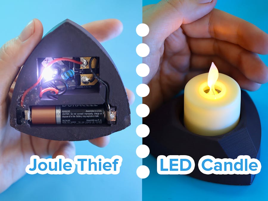
Earlier this year, I created a circuit board for the classic "Joule Thief" circuit, which allows you to run small projects off of nearly-dead batteries (including AA, AAA, and CR2032). I've now combined that PCB with a 3D-printed holder for LED tea lights; with a few small modifications, the lights will now run off of "dead" batteries and can be switched on and off from the bottom of the holder. Let's go!
Here's an overview of the project and how I put it together:
3D-printed partsAs usual, I've modeled this project in OnShape (grab it here!). There are two parts: the main body and a small clip that provides the "spring" to hold the battery in place. With the spring as a separate part, it can be adjusted to hold different battery sizes, and it also works better than any method I could invent to print it all in one piece (considering the support material and ease of battery insertion/removal).
Above: top view of the model – a reuleaux triangle (or close enough) with facets cut out and a circular depression for the candle. In the depression, a slot is added to pass wires through to the bottom. To the left is the spring clip, modeled on its side so that it will print in a strong orientation.
Below: bottom view of the model – showing rectangular cutouts for the Joule Thief PCB and battery, plus adjoining small cutouts for the power switch and spring clip and rounded ones for the wires.
In keeping with the sustainability theme that inspired both the PCB and this design, I'm printing this with Closed Loop U-HIPS recycled filament (Nebula Black, which comes out a sort of deep matte plum).
The circuitI'm modifying a few different LED tea lights to attach to this holder. That's easy: just pop the bottom battery cover off, pull out any CR2032 battery that may be in there, and solder wires to the positive and negative battery contacts. Also, make sure the power switch is left ON.
Then, we push those wires through the slot in the 3D-printed holder, to the bottom. Solder them to the LED contacts on the Joule Thief PCB (with an eye to polarity). In this way, the tea light takes the place of the LED – though, since the circuit has plenty of juice, I've also left the original LED in place on my tester unit.
Taking two more wires, we solder them to the positive and negative contacts of the Joule Thief, then route them through the channels in the holder. The positive wire is routed through a switch, which is then soldered to a bit of conductive copper tape stuck inside the battery compartment. On the opposite end, the ground wire is routed directly to conductive tape on the opposite end of the battery compartment.
...Diagrams coming soon! :D


Comments
Please log in or sign up to comment.