


Hardware components | ||||||
_baVEVgguW1.jpg?auto=compress%2Cformat&w=48&h=48&fit=fill&bg=ffffff) |
| × | 1 | |||
 |
| × | 1 | |||
 |
| × | 1 | |||
 |
| × | 1 | |||
 |
| × | 1 | |||
 |
| × | 1 | |||
Software apps and online services | ||||||
 |
| |||||
Hand tools and fabrication machines | ||||||
 |
| |||||
So you want to be an LED superstar? Start here.
First off, consider the throwie: a simple, fun circuit that lets you light up the town.
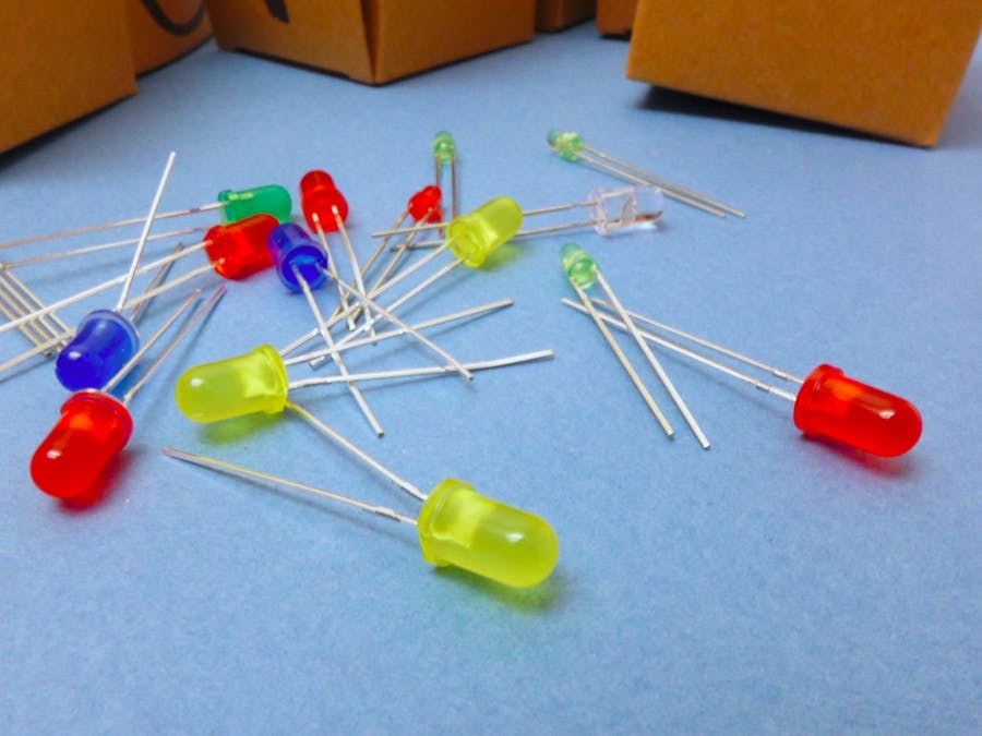
Grab your LED and check it out. One long leg and one short. The long leg is positive. The short leg is negative, and you can remember because that side of the LED is slightly flattened, like a –.
Pick up your coin-cell battery. It's got a flat side with some writing on it, and a ridge running around the opposite side. The flat side has a big + on it: positive.
Stick the battery in between the leads on the LED, so that the battery's positive side touches the positive leg on the LED. Fiat lux!
If you want, you can wrap some tape around the unit – to keep it together and isolate the circuit from the external world – and attach a magnet to it, then stick it somewhere mischievous.
Great! But what if you want to turn it on and off? Pulling out and replacing the battery isn't much fun. For long. For most people.
Let's make it smart with Arduino!
SetupBust out your laptop and install the latest complete version of the Arduino IDE, from the top of this page: https://www.arduino.cc/en/Main/Software
Plug your Arduino board into a USB port on your computer.
Get out your components.
All set!
Build itLoad up Arduino's built-in example at File > Examples > Basics > Blink
Like most Arduino boards, the Uno comes with a built-in LED that's connected to digital pin 13. Upload the code and watch it flash on and off, changing once per second.
Now, do the same thing with an external LED! Grab yours and plug the long positive leg into the header at digital pin 13. Plug the short leg into the GND (ground) header. You can also move the positive leg to any of the other digital pins, and change the "13" in your code to match.
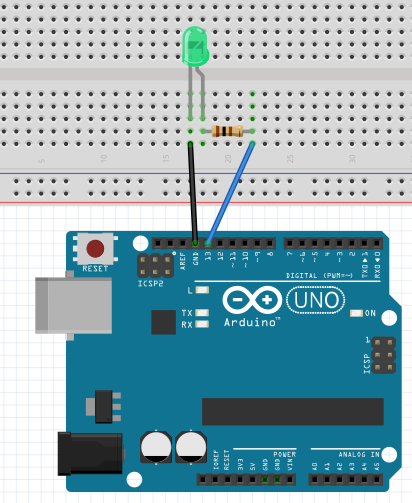
But running your Arduino this way lets too much power flow through the circuit, and can burn out the LED – or the microcontroller pin itself. Let's add a resistor before moving on: move the LED to a breadboard, with each leg in a different 5-hole row. Add a jumper wire connecting the negative leg to GND. Place another wire from digital pin 13 to an empty row, then connect that with the LED's positive leg using your resistor. (The resistor can go either way around.)
Here's some more info on why we really do need the resistor.
CODE
So! What are we actually doing here?
The code starts with some introductory notes, which are commented out with slashes and asterisks: one of two ways to tell the machine, "this piece is for humans – ignore." Well-commented code is a great way to make sure others can understand and modify it later.
The Arduino-friendly part begins with a setup section, which runs first, each time you power on the board (or press reset). This is where you tell the Arduino what's connected to it: inputs such as sensors, outputs such as displays, and more. In our setup section, we're telling it that there is a controllable output on digital pin 13.
Once setup is done, the loop section takes over and (as the name implies) runs over and over again until the board is powered off. Our loop turns the LED on (HIGH) or off (LOW) every 1 second (1000 milliseconds).
Adapt thisIt's not all about LEDs. Well, it's mostly about LEDs. ;) But here are some more things you can do with the Blink sketch:
- Add more LEDs on different digital pins, change the on/off durations, and create a Pomodoro timer
- Make a sleep/wake timer using a haptic motor in place of the LED
Let's move on to adding a button!
Or, learn to blink this LED via Javascript with our NodeBots tutorial.
Learn to decipher the resistor number/color code here.
See the whole series of Hackster 101 tutorials on Hackster and YouTube


Comments