/* This expirement requires:
1x arduino (UNO)
1x integrated circuit ic74hc595 (IC7)
1x 7 segment common cathode display (SSD)
1X breadboard (BBD)
8x 220k resistors (RES)
a bunch x wires/jumpers
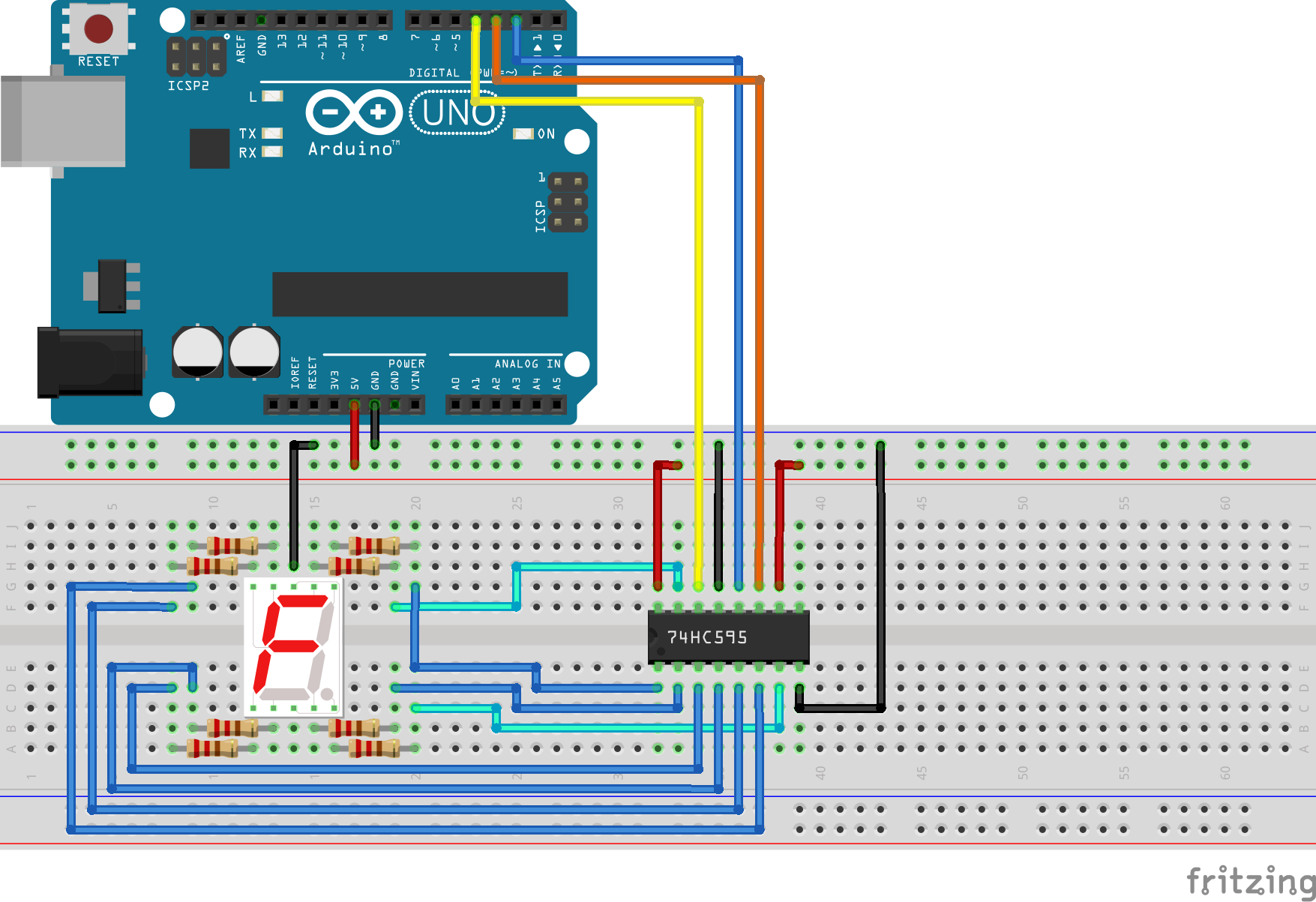
++Scroll to bottom for wiring schematic++
++and lighting math table++
*/
int latchPin = 2; //tells IC7 to dump stored data to SSD (pin2 UNO > pin12 on the IC7)
int dataPin = 3; //data from arduino to IC7 (pin3 UNO > pin14 IC7)
int clockPin = 4; //clock from arduino to IC7 (pin4 UNO > pin11 IC7)
/*The next line creates an array.
Basically, an array is a spreadsheet that has Cols, Rows and a dozen or more pages.
Note: The below table contains 18 characters, The index though starts at 0.
So the 16th character, (int upArray[16]) would return 127.
arRay[3][4][5] is a valid array. (arRay[0,1,2]) returns 1st Col, 2nd Row, 3rd Page.
*/
const byte upArray[18] = {1, 2, 4, 8, 16, 32, 64, 128, 63, 6, 91, 79, 102, 109, 125, 7, 127, 111};
/* These numbers corrospond to the sum of the SSD's pin address.
For instance, the number 1 needs to supply a low signal to pins B and C.
Each pin is an increase of *2. pinA = 1, pinB = 2, PinC = 4, PinD = 8, PinE = 16 and so on.
So to display a 1 you will need to light up segmentB and segmentC = 2 + 4 = 6
6 will need to be send to the IC7 to tell it to display 1 on the SSD.
The "." (decimal) = pinPD or the 8th pin or 1*2*2*2*2*2*2*2 or 128.
2 lights up pins A, B, D, E & G. or 1 + 2 + 8, 16 & 64. So, send the sum 91.
*/
void setup() {
Serial.begin(9600); //This sets up the UNO to send information to you're IDE's serial display
pinMode(latchPin, OUTPUT); //Sets your UNO pins to OUTPUTs from INPUTs (default)
pinMode(dataPin, OUTPUT); //You want to send data to the IC7, not receive data
pinMode(clockPin, OUTPUT); //like you would for, perhaps, a sensor.
}
void loop() {
for (int j = 0; j <= 17; j++) { //sets j to number 0; if j <= 17; increase j by 1
//do the stuff in the {brackets}
digitalWrite(latchPin, LOW); //remember, when the latch is HIGH, the IC7 is dumping data to the SSD
shiftOut(dataPin, clockPin, MSBFIRST, upArray[j]); //send data, your totals, from the UNO to the IC7
digitalWrite(latchPin, HIGH); //UNO tells IC7 to send the decoded totals to the SSD
Serial.println(upArray[j]); //Print (upArray[j]) to your IDE's serial display
delay(1000); //A 1 second delay, then check if j less than or equal to 17 again
}
}
/* blank = no connection
* <r> resistor between connections
SSD : RES : IC7 : UNO : BBD
---------------------------
A : <r> : 15 : :
B : <r> : 1 : :
C : <r> : 2 : :
D : <r> : 3 : :
E : <r> : 4 : :
F : <r> : 5 : :
G : <r> : 6 : :
DP : <r> : 7 : :
GND: : : : GND
: : 8 : : GND
: : 9 : : : NOT USED
: : 10 : : +5V
: : 11 : 4 :
: : 12 : 2 :
: : 13 : : GND
: : 14 : 3 :
: : 16 : : +5V
: : : +5V : +5V
: : : GND : GND
----------------------------------
Maths table:
|A|B|C|D| E| F| G| PD|ttl1
|1|2|4|8|16|32|64|128|
0|1|2|4|8|16|32| 0| 0|63
1|0|2|4|0| 0| 0| 0| 0|6
2|1|2|0|8|16| 0|64| 0|91
3|1|2|4|8| 0| 0|64| 0|79
4|0|2|4|0| 0|32|64| 0|102
5|1|0|4|8| 0|32|64| 0|109
6|1|0|4|8|16|32|64| 0|125
7|1|2|4|0| 0| 0| 0| 0|7
8|1|2|4|8|16|32|64| 0|127
9|1|2|4|8| 0|32|64| 0|111
.|0|0|0|0| 0| 0| 0|128|128
*/


_ztBMuBhMHo.jpg?auto=compress%2Cformat&w=48&h=48&fit=fill&bg=ffffff)


Comments
Please log in or sign up to comment.