Motivated by success on other acoustic projects and by this brain transplant blog, a sonar project sprang to mind.
A phased array sonar works in the same way as a phased array radar. Rather rotating the sensor to look direction, this is achieved by combining the signals from an array of fixed sensors each with different phases. Normally a large number (100s) of sensors are used. In astrophysics they are randomly sparsely populated. In this project only two ultrasonic receivers are used. Only one transmitter is used.
The existing HC-SR04 sends out 8 40kHz pulses. In this hack, I'm replacing it with binary phased shifted key (BPSK) m-sequence with each key consisting of 5 pulses. This has better signal properties.
Existing HC-SR04 signals
The following are diagrams that come from an unmodified HC-SR04
You can see how the transducer continues to resonate after the max232 chip has finished sending the train of 8 pulses to the transducer.
New Sonar Pulse
The following is the binary phased shifted key signal using a m-sequence of the value (-1,1,-1,-1,1,1,1). You can see the phase changes if you look closely enough...
It is considerably longer than the 8 pulses of the original and this impacts its minimum range.
This is what it looks like when it goes to the transducer...
This is what it looks like when it is received (in the red box)...
The reason why you see the three bulbs in the received signal is due to the phase change. The three bulbs you see before is the transmission through the PCB. In the non hacked HC-SR04, the comparator is turned off so it does not see this.
Producing the signal on the Launchpad
The pulse train and the power to the max232 chip is produced using the PWMs on the launchpad. One of the PWM produces the 40 kHz carrier while another produces the 8Khz phase modulation that depending on the current state of the m sequence is -ve or +ve, it inverts the 40 kHz carrier PWM signal. You can view the code to see exactly how this is done.
Hacking the HC-SR04
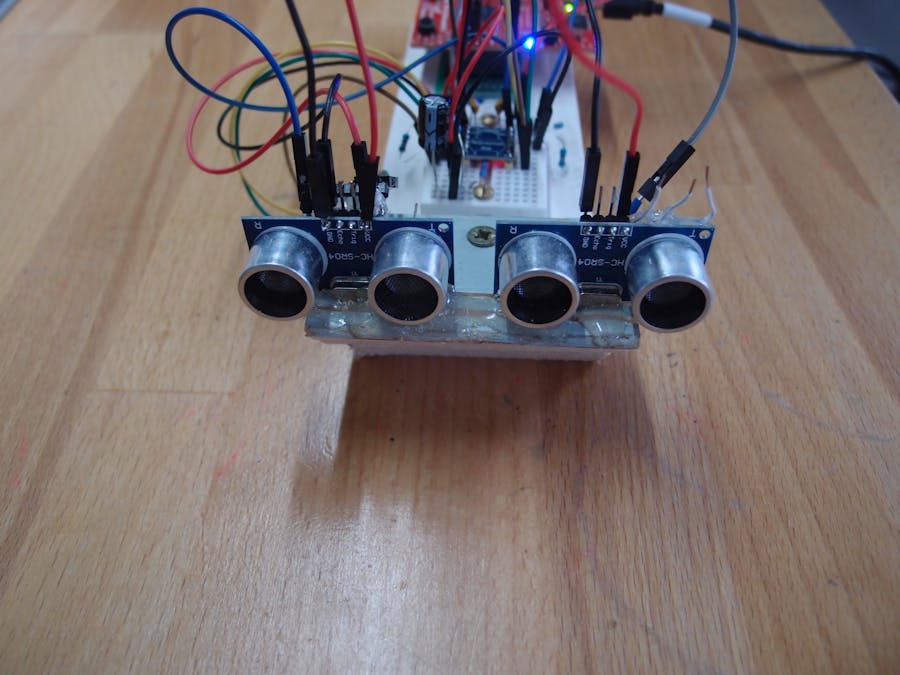
On one of the HC-SR04s I simply removed the CPU and put in jumper wires to access the T1IN and T2IN and power to the MAX232 chip. I also accessed the received signal after all the op-amp amplifier, but before it went into the comparator (white wire). It is a bit of a mess. On the other HC-SR04, I just access this sample receive signal.
Launch Pad
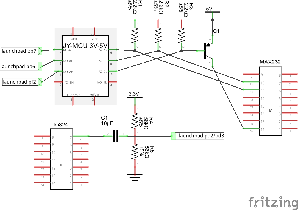
The launchpad operates at 3.3V while the HC-SR04 operates at 5Vs so I used the standard MOSFET based level converter PCB to convert the signals. I found the 10K ohm pull ups were introducing too much slew, so I supplemented them with 2.2K ohm pull ups. I'm not sure if it was actually needed, but that looked better on the oscilloscope.
The output of the 3rd opamp on the lm324 chip is connected to the analogue to digital converter on the launchpad. The signal has to be re-biased to suit the launchpad using a resister divider network. 56K ohms were used arbitrarily, they just need to be be high values. The 10uF ceramic was used because that is the max value of a non-polarized ceramic cap.
Processing the Input
The signal from the HC-SR04 module goes into the two of the analogue to digital converters on the launchpad. It goes through what is called an I/Q de modulator stage. which given we are using a binary and not quadrature phase modulation means that we just multiple every second sample by negative one. Again, you can view the code to see exactly how this is done.
You can kind of make out the m-sequence the progressively bigger humps. You can also see that one is 180 degrees out of phase of the other.
For reference, the following is a demodulation of the original 10 pulses...
After demodulation comes the correlation to the m-sequence. It is not a sharp peak, but it is a peak none the less... This correlation gives the range to the target.
Phased Array
The phased array works by correlating the sum of the two inputs with a phase difference. The phase difference effectively works by re-enforcing a signal. The correlation that produces the highest value indicates the direction to target. The graph below shows two sets of 65 correlations. One where the bottle is in position A and the other in position B. You can see why normally such phase array setups have many sensors. If mine did, you would see a much strong peak. But still bats survive quite well with just two ears. I guess they benefit from fast update rates and some sort of Markov processing.
Bottle positions
Increased Range
With the "better signal" comes a higher performance signal. This is what the correlation looks like after reflecting off a wall at 4.6 meters...


Comments
Please log in or sign up to comment.