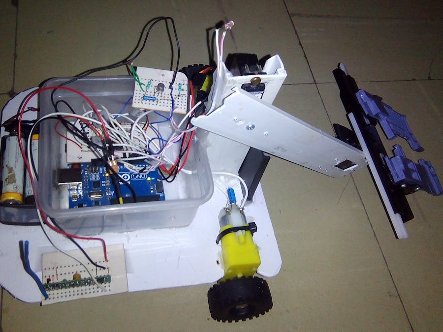
To achieve my goals, we divide the project into two parts: the transmitting part and the receiving part. In the transmitting part I use the "Infineon 3D Magnetic Sensor 2Go" board to capture and process the data that this sensor gave me and I use the "Mega 2560" board to send this data by “Radio Frequency”. In the receiving part I use the "Arduino UNO" board to execute the received orders. To make this prototype, I was inspired by my project:
We have to review the technical sheet of our magnetic sensor. In the following image we can see the components of this board.
In the following image we can see the configuration of the pins of our board.
To program our board, we have to download and install the following software:
- Arduino IDE.
- 3D Magnetic Sensor 2 Go.
- USB Driver from SEGGER.
- Library: TLE493D-W2B6-3DMagnetic-Sensor
- Board: XMC Microcontroller by Infineon
The latest version of Arduino IDE is downloaded from: https://www.arduino.cc/en/Main/Software
3D Magnetic Sensor 2 Go, serves us to test with our device and download it from the official site of Infineon. This program only runs under Windows and has an old USB version of SEGGER. We have to download and install the latest version of SEGGER USB Driver so that our device works correctly.
The library TLE493D-W2B6-3DMagnetic-Sensor is downloaded from: https://github.com/Infineon/TLE493D-W2B6-3DMagnetic-Sensor
The Microcontroller board is downloaded from the official Infineon site on github. There we will find the instructions for a correct installation.
https://github.com/Infineon/XMC-for-Arduino
In my case, I installed version 1.1.0 since version 1.1.1 indicated an error. Later we added the url of the card and installed it: https://github.com/Infineon/Assets/releases/download/current/package_infineon_index.json
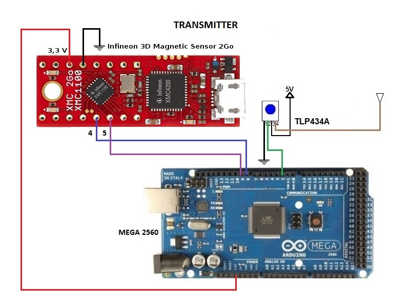
Theelectrical diagram of the “RF Transmitter” is as follows:
The operation of the RF Transmitter is as follows:
We rotate the "Rotation Knob" of our magnetic sensor and we can execute four orders that are programmed by software and using the GPIO4 and GPIO5 pins as outputs:
- Stop: order to stop the car and send the code "00".
- Right: order to turn the car to the right and send the code "01".
- Forward: order to go forward and send the code "10".
- Left: order to turn the car to the left and send the code "11".
Infineon.ino
#include <Tle493d_w2b6.h>
Tle493d_w2b6 Tle493dMagnetic3DSensor = Tle493d_w2b6();
void setup() {
 Serial.begin(9600);
 pinMode (4,OUTPUT);
 pinMode (5,OUTPUT);
 while (!Serial);
 Tle493dMagnetic3DSensor.begin();
 Tle493dMagnetic3DSensor.enableTemp();
}
The board receives these four orders from the magnetic sensor, encodes them and sends them through the transmitter "TLP434A", which works at 433 MHz. These encodings are the following:
- Stop: we send the character "S".
- Right: we send the character "R".
- Forward: we send the character "F".
- Left: we send the character "L".
We can use several libraries to validate the data sent by Radio Frequency, in my case I have used the library "VirtualWire.h" and this library works very well. The codes of the boards "Infineon 3D Magnetic Sensor 2Go" and "Mega 2560" can be downloaded at the end of this tutorial.
TX_mega.ino
#include <VirtualWire.h>
#define SWITCH1 8   //input for SWITCH1
#define SWITCH2 9   //input for SWITCH2
void setup()
{
   Serial.begin(9600);
   Serial.println("Tx RF");
   pinMode (SWITCH1,INPUT);
   pinMode (SWITCH2,INPUT);
   // Se inicializa el RF
   vw_setup(2000); // bps
   vw_set_tx_pin(2); //output RF
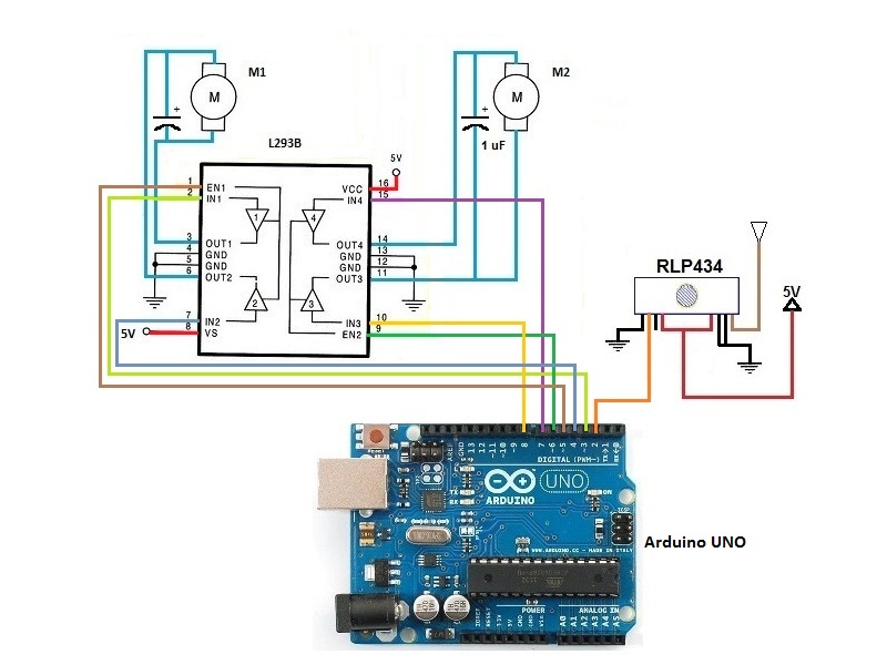
}The diagram of the “RF Receiver” is as follows:
The operation of the RF Receiver is as follows:
The "Arduino UNO" board receives four orders from the RF Transmitter through the receiver "RLP434", which works at 433 MHz. These commands are decoded and executed in the following way:
- Stop: we receive the character "S" and the car stops.
- Right: we receive the character "R" and the car turns to the right.
- Forward: we receive the character "F" and the car moves forward.
- Left: we receive the character "L" and the car moves to the left.
Each time the car moves, we use the "L293B" driver and two reduction motors.
We can use several libraries to validate the data sent by Radio Frequency; in my case I have used the library "VirtualWire.h" and this library works very well. The code of the "Arduino UNO" board can be downloaded at the end of this tutorial.
Rx_arduino.ino
#include <VirtualWire.h>
void setup()
{
   Serial.begin(9600);  // Debugging only
   Serial.println("setup");
   // Se inicializa el RF
   vw_setup(2000);  // bps
   vw_set_rx_pin(2);  //Pin 2 as input RF
   vw_rx_start();       // start
  pinMode(3,OUTPUT);
  pinMode(4,OUTPUT);
  pinMode(5,OUTPUT);
  pinMode(6,OUTPUT);
  pinMode(7,OUTPUT);
  pinMode(8,OUTPUT);
}
Test
Conclusions
I first tested the prototype with the devices connected to my PC to verify that the communication was being made and that the "RF Receiver" received the data that the "RF Transmitter" was sending. The serial port of the Arduino UNO board shows us this data that I was waiting for. In the second test I used a prototype of a "Microrobot Car" to demonstrate an application of this prototype.
Using the "Infineon 3D Magnetic Sensor 2Go" board in a remote control is a good option to control a "Micro Robot Car", since it gives you the opportunity to maneuver your cart in a practical and efficient way.


_ztBMuBhMHo.jpg?auto=compress%2Cformat&w=48&h=48&fit=fill&bg=ffffff)
_wzec989qrF.jpg?auto=compress%2Cformat&w=48&h=48&fit=fill&bg=ffffff)


Comments