In this project, we use an Arduino Uno to build an autonomous "follow me" cooler. The robot cooler connects to a smartphone via Bluetooth and uses GPS to navigate. All the electronics will be contained in the base so that other objects can be carried as well.
Find all the 3D printable parts for this project on our Patreon: https://www.patreon.com/posts/follow-me-cooler-37733146
How We Built ItWe created two videos about the build process for this project. In this first video, Davis explains how to build the base.
To construct the base, we used a large piece of scrap 1/4" MDF board and a couple 1x3" planks to serve as the sidewalls. Standing the boards up on end to create a box helped keep the cooler in place while the base was moving.
We measured the MDF to be about 1 inch larger on each side than the dimensions of the bottom of the cooler. In this case, the cooler was 17.5x11.5", so we cut the MDF to be about 19.5x13.5". The extra space allowed the 1x3" boards to be nailed on top of the MDF. Our jigsaw worked well to cut this piece.
The 1x3" planks were cut to the same length as the depth of the base, but we made them about 2 inches shorter on the width so that they could align with the edges of the MDF. The planks were attached to the MDF with a few small nails.
In order to house the electronics, we made a small box using the same process as the base platform (albeit using some 1x2" planks instead of 1x3"). We eyeballed the dimensions here, but it turned out to be about 11x9". The electronics box was nailed to the bottom of our platform after we cut a hole in the MDF with our jigsaw.
Finally, we added the components for the drive system. The wheels used a couple 3D printed brackets (3D parts provided below) to mount our high torque 12v motors. A 3D printed connector was attached to a metal hub to mount the wheel on the motor shafts.
A simple swivel wheel was used on the back of the platform. It was attached with another 3D printed bracket.
In the second video, Aaron adds the electronics to the base of the cooler.
The electronics were installed in the box cutout under the platform. We used an Arduino Uno and a 5v battery to power the sensors, Bluetooth, and control logic. A 3s LiPo battery was used to power the motors.
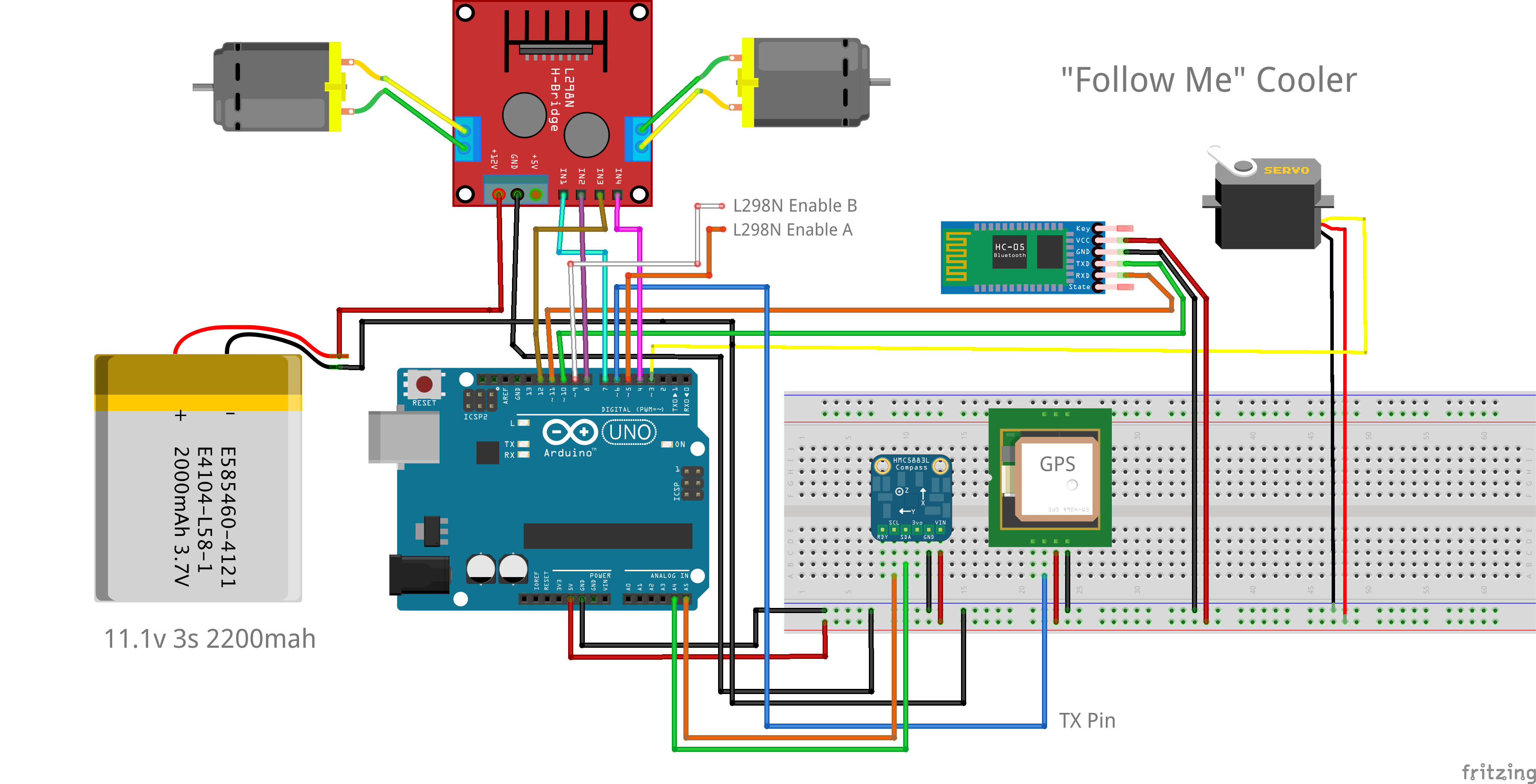
A HC-05 Bluetooth module was mounted at the front of the platform for better range. The rest of the components including a L298N motor driver, PAM-7Q GPS, and HMC6883L compass were mounted inside and connected to the Arduino through the breadboard.
The compass works with I2C, so we connected the SLC and SDA pins to A5 and A4 respectively. The rest of the pins were connected through digital I/O. For more information on how we connected the wires, see the diagrams provided in the schematics section below.
The motors were powered by drilling holes through the platform and attaching them the L298N motor driver board. The 3s LiPo was connected as the main power source and we tied the ground together with the Arduino power source for control logic.
The following image shows what everything looked like once it was connected in the electronics box.
The motorized lid wasn't included in either of our build videos, so we posted some supplemental instructions on how to add it.
Our cooler lid had a couple notches that kept the lid snapped shut when it closed. Our servo wasn't strong enough to lift the lid when it was snapped shut, so we used a small Dremel tool to sand down the notches.
We used a MG996R high torque servo power the lid. We 3d printed a hinged arm to connect the servo horn to the top of the cooler. In order to keep it in place, we used some gorilla glue. The servo was mounted on the side of the cooler with a piece of 3M double sided outdoor mounting tape.
A hole was drilled on the back of the cooler to feed the servo wires through. We used a couple of extension wires to attach it to power, ground, and the signal wire pin 3 on the Arduino.
This is the configuration we used for our Blynk app.
Once you have everything configured property, verify and upload the code to your Arduino. If you are outside, it will take a few seconds for the GPS to acquire a satellite lock. Once it does, it will begin flashing.
Make sure your Android device is paired with HC-05 Bluetooth module. If it asks for a password, it should be default 1234. Open Blynk and press play!
All of the code for this project is provided open source on our Github page. For more instructions on how to use it, view the README.md.
Cheers,
Aaron @ Hacker Shack


_ztBMuBhMHo.jpg?auto=compress%2Cformat&w=48&h=48&fit=fill&bg=ffffff)


Comments
Please log in or sign up to comment.