


Hardware components | ||||||
_baVEVgguW1.jpg?auto=compress%2Cformat&w=48&h=48&fit=fill&bg=ffffff) |
| × | 1 | |||
| × | 1 | ||||
| × | 1 | ||||
| × | 1 | ||||
| × | 4 | ||||
| × | 4 | ||||
| × | 4 | ||||
| × | 12 | ||||
| × | 4 | ||||
| × | 2 | ||||
| × | 1 | ||||
| × | 2 | ||||
Hand tools and fabrication machines | ||||||
 |
| |||||
 |
| |||||
| ||||||
I am going to go ahead and post this, but I will update with a video on the new I2C compass and code improvements later on (my bench is getting messy).
Overview:We wanted to add a twist to our rover, so we decided on pursuing a Mecanum wheeled drive train. This system provides a method of strafing in addition to traditional propulsion and rotation.
Julio started us off by demonstrating some wheels he had printed up that fit the axles connected to the DC motor gearboxes we were provided in the supplied kit.
We were able to get a basic rover wired up and the wheels fitted to the chassis, but we soon realized that our strafing movements were neither balanced nor predictable.
Frustrated, we looked for alternatives. We ended up using some wheels from VEX Robotics, and it looked like we would be able to achieve more consistent results. This, however, led us to our next problem: the wheelbase of the chassis we had been using was not long enough to accomodate the 4" wheels.
Bruce, after putting up with a lot of my shoddy Meshmixer work, printed up an amazing chassis that he found on Thingiverse. It fit the VEX wheels perfectly, and allowed us to finish up the core physical framework of the rover. (Much thanks to Bruce on this one, as it ended up being over an 18 hour print job!)
Bruce's printing notes: This was quite complicated to print. I used supports naturally, but no bed attachment options. In retrospect, a raft would have helped greatly. I kept a regular watch on this, and a couple of times had to quickly glue down to the print bed a clump of support material that had detached itself. Overall, it turned out a lot better than I thought it would. I printed this in PLA since that is what I have experience with, and it seems to be robust enough for the build.
This got us to the point where we could run basic cardinal movement tests and verify that we had a solid concept going forward.
Arduino 101:We decided that we wanted to use a "field-centric" control scheme. This allows the rover to maneuver in a direction regardless of current rotation while retaining the point of reference of the operator. In simple terms, we augment the "forward" and "sideways" input values with the gyroscope heading. Using this method, the "virtual front" of the rover will always be facing away from the operator.
Rather, we employed a dual stick approach with the left stick controlling direction and the x-axis on the right controlling rotation. In order to implement this properly, we needed to access the IMU (Inertial Measurement Unit) on the Curie. We will get back to the IMU in a bit, but in the meantime, here is a quick video of what this allowed us to do.
We also wanted to retain the traditional method of driving (primarily for base testing), so we just went with the ability to toggle between modes using the tab widget in Blynk.
Blynk Local Server:We wanted to be able to demo the Meca-ROV while we were out and about, and we didn't want to have to deal with certain "flooding" limitations imposed by the Blynk cloud service, so we set up a Local Blynk server on a Raspberry Pi. We used a 2.2" TFT screen to display tails of logs and facilitate wifi setup and modifications. As it is not a touchscreen, we used a small bluetooth keyboard for times that we couldn't ssh/vnc in. Both the Pi and the Remote are tethered to a mobile hotspot.
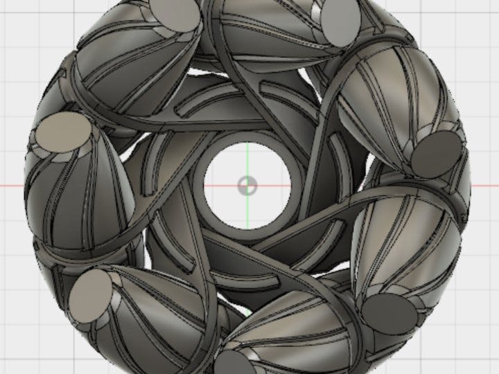
We used a 3D printer for a few crucial parts of our build, the Wheels and a Battery holder. We found some suitable wheel parts on thingiverse.com:
The following wheel adapters fit the bot motors: http://www.thingiverse.com/thing:1785103
Then you can proceed in printing the rest of the wheels: http://www.thingiverse.com/thing:1454685
We decided early on to use 18650s to provide an adequate power supply. Julio printed us out some casings that could easily be wired serially or in parallel. For reliability, it really makes sense to run your drive system off a different power supply as your Arduino. Your motors will be rated with a "Stall Current" and a "Free Current".
- Stall current is the maximum current drawn(1), when the motor is applying its maximum torque, either because it is being prevented from moving entirely or because it can no longer accelerate given the load it is under.
- Free current is the current drawn when the motor is rotating freely at maximum speed, under no load(2) other than friction and back-emf forces in the motor itself.
1: Under normal conditions, i.e. the motor isn't being asked go from max speed in one direction to max speed in the other.
2: This assumes the motor is not being driven by external forces.
(http://robotics.stackexchange.com/a/615)
There are situations where this is easily surpassed, such as when quickly reversing the direction of a motor at full throttle. (This should be avoided, and a ramping algorithm would ideally be in place.) If both the Arduino and the motors/controllers are being run off of a single power source, this can very often lead to "brownouts" of the Arduino, which will leave your bot dead in the water.
http://www.thingiverse.com/thing:456900


_3u05Tpwasz.png?auto=compress%2Cformat&w=40&h=40&fit=fillmax&bg=fff&dpr=2)
Comments
Please log in or sign up to comment.