

Hardware components | ||||||
_ztBMuBhMHo.jpg?auto=compress%2Cformat&w=48&h=48&fit=fill&bg=ffffff) |
| × | 1 | |||
 |
| × | 1 | |||
 |
| × | 1 | |||
 |
| × | 1 | |||
| × | 1 | ||||
| × | 1 | ||||
 |
| × | 1 | |||
 |
| × | 2 | |||
 |
| × | 14 | |||
 |
| × | 10 | |||
 |
| × | 10 | |||
 |
| × | 1 | |||
 |
| × | 1 | |||
| × | 1 | ||||
Hand tools and fabrication machines | ||||||
 |
| |||||
 |
| |||||
A light sensitive sampling process Microcontroller Software and Hardware Application (MSHA) project.
It measures the Sun's light strength through a simple sampling process and every time 3600000 cycles are detected by microcontroller, 1 Heliograde is added. Maximum 10 Heliogrades / day. Each time 1 Heliograde is added, one more LED illuminates (until maximum 10 is reached).
DifficultyNOT for beginners. Amateurs and advanced.
General StructureIt consists of 2 boards:
- Arduino (all boards) or any microcontroller
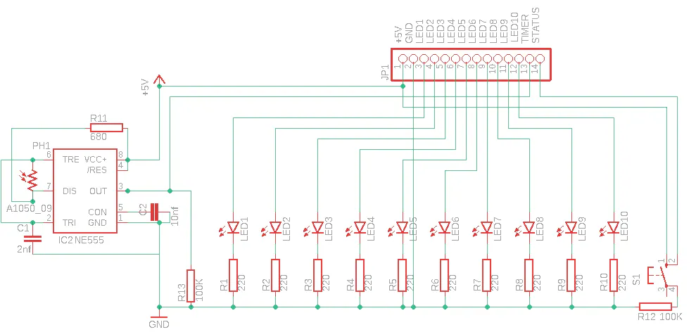
- A custom Helioboard (see schematic)
The installed NE555P (recommended) timer on the Helioboard oscillates (astable mode) as defined by the photoresistor's luminosity:
- High luminosity: ~1.2MHz
- Low luminosity: <100Hz
As we can see for sure, the strongest natural light in our world is the Sun's one. So, the maximum frequency of 1.2MHz can be achieved for sure, if the Helioboard is placed anywhere that can get hit by Sun rays! Of course, we strongly recommend that you place the board in inner rooms behind a window, so no damage happens. The microcontroller board on the other hand, should be placed out of the sun rayed region, as it could be at high risk while exposed to the Sun. So, try to connect the two boards around 20cm (min) - 50cm (max) apart from one another. Longer distance between them can cause false data reading as long cables cause noise.
Get the Helioboard3 ways to get your own Helioboard:
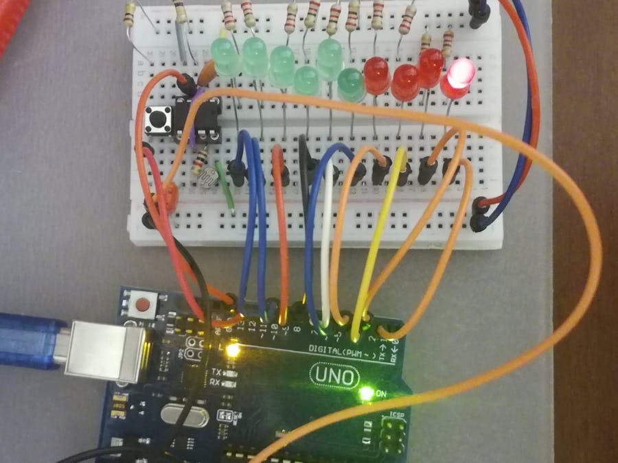
- Create your own Helioboard on a breadboard as the schematic shows (amateur and advanced)
- Solder the components to a Veroboard as the schematic shows (a bit advanced)
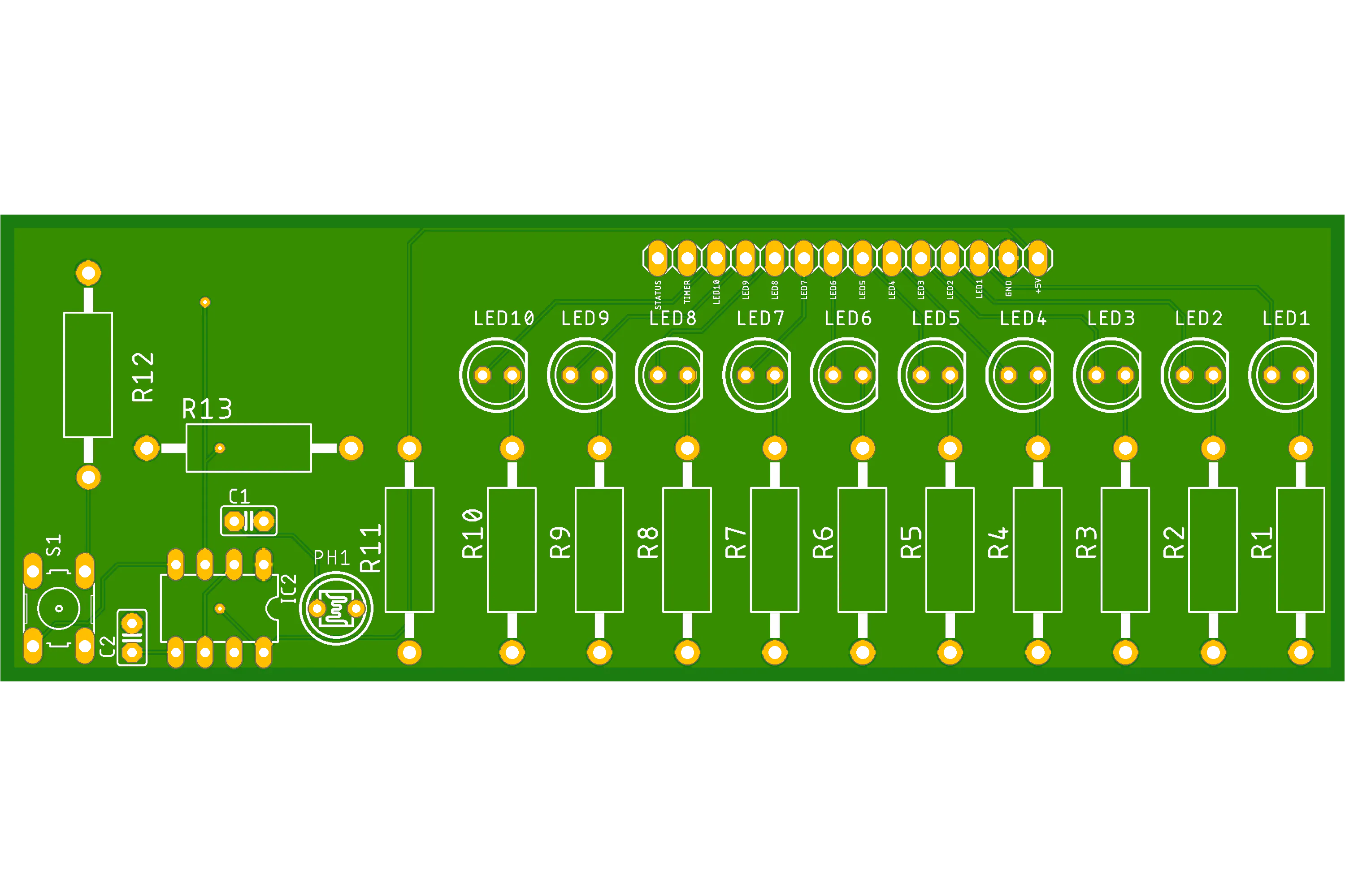
- Download the CAM Outputs.zip folder from below so you send the data to a company to build the PCB or DIY!
ConnectionsConsidering that this first version of the project is arranged for Arduino board (UNO specifically), connections guide is about UNO pins.
1. Get a multicable of 14 or 14 soft single jumpers (male to male)
2. Connect their male edges to each of the 14 available pinheads on the Helioboard
3. Take the first 2 on the Helioboard that are connected to +5V and GND pinheads and connect them to the corresponding pinheads on the UNO board.
4. Take the other 2 on the other side of the pinhead array on the Helioboard that are connected to the STATUS and TIMER pinheads and connect them to pins 12 and 13 of the UNO board correspondingly
5. Take all the rest 10 hanging jumpers and connect them to the middle 10 available digital UNO pins.
Make it workIn order to make the hardware work, the last step is to upload the code to the UNO and done! *.*
1. Download the code from the Code section of the project in your preferred folder on your computer
2. Open the file in your Arduino IDE and connect your UNO to the computer with the USB cable
3. Go to Tools on the Menu bar and select the correct Board and Port
4. Click the Verify button on the upper left corner of the IDE so you check no errors occurred
5. If alright, click the Upload button to upload the code
6. Wait until all the 10 LEDs blink for half a second and that's it!
7. If connected to a pc or other digital processor unit through the USB cable, open the Serial monitor on the IDE and you can press anytime the small STATUS button on the Helioboard to see the progress status
Thank you for preferring my project! :)
Hope you enjoy it.
The author, Argyrios Pournaris


Comments
Please log in or sign up to comment.