


Hardware components | ||||||
 |
| × | 1 | |||
| × | 38 | ||||
| × | 1 | ||||
| × | 1 | ||||
_iTuZ3KHU3i.png?auto=compress%2Cformat&w=48&h=48&fit=fill&bg=ffffff) |
| × | 1 | |||
Software apps and online services | ||||||
_4YUDWziWQ8.png?auto=compress%2Cformat&w=48&h=48&fit=fill&bg=ffffff) |
| |||||
| ||||||
| ||||||
| ||||||
In my experience, weather stations with outside temperature sensors work for about two minutes before either the RF link doesn't work anymore or the battery is depleted. Before buying the hundredth station, I decided to build something myself. And why should I need to rely on an outside sensor when I have something better that is not limited to the current temperature and can also do forecasts... The INTERNET! ;-)
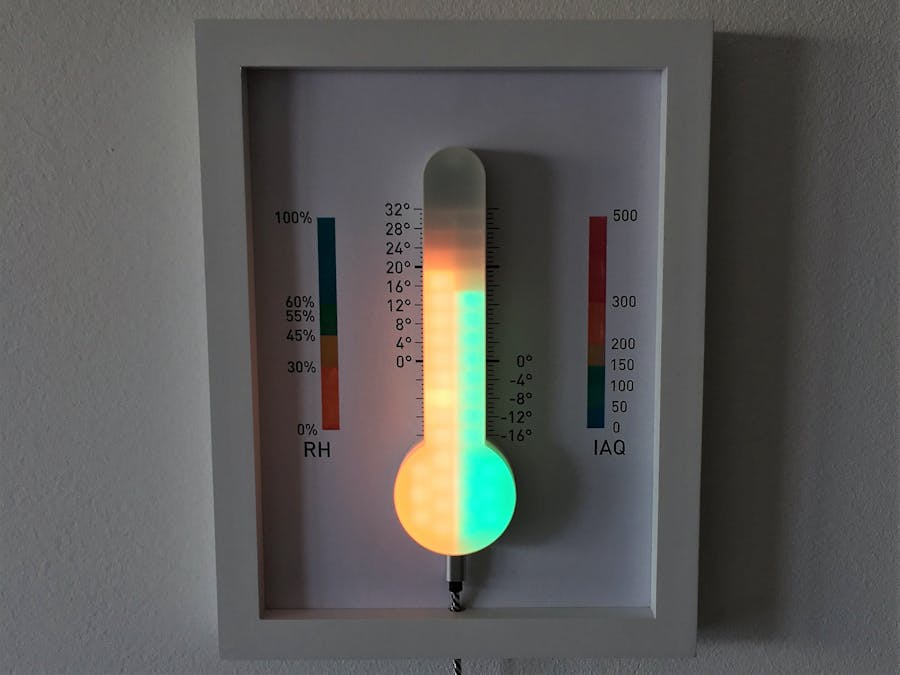
In terms of display, I wanted to create something that is not looking the same as other weather stations out there and that is more alike to traditional thermometers and displays temperature in a bar-graph-like manner. At the same time, more than one parameter should be displayed simultaneously, e.g. inside & outside temperature as well as humidity and air quality. So I decided to go for NeoPixels, to be able to use level and color to convey information.
The ThermoLight can display up to four values, 2x by means of the bar-graph height, 2x by means of the NeoPixel colors. Both the bar-graphs as well as background colors can be configured individually via webinterface. As the bar-graph step size can be quite large from one LED to the other, the top LED will start blinking up to three times to indicate in-between values.
- Display in the form of a classical thermometer with approximately 1 degree resolution, using NeoPixels
- The ability to display up to four different values easily and combine different information like e.g. temperature & humidity
- On-board sensors for temperature, humidity and air quality
- Internet connectivity to get information from weather APIs or MQTT and send on-board sensor values to storage (e.g. InfluxDB server)
- Configurable via webinterface & "living-room-ready" with a nice enclosure
MCU: The project is based on an ESP-12S (I talked about some of the reasons in my previous project IRBridge) and again uses a micro-USB-port for supplying power.
Display: As I wanted to have a very specific geometry resembling a classical thermometer, I chose not to use any ready-made LED rings, matrices or strips and opted for a custom PCB design that uses 5050 SMD NeoPixels (aka WS2812B). Hand soldering them is quite easy, however be careful with ground/power planes. In my design with a ground plane I found it best to first tin and solder the ground pad as it needed extra heating as compared to the other pads.
Sensors: To sense temperature and humidity, a SHT 31-D was chosen due to its good sensitivity/accuracy and it being I2C. For air quality, I opted for a CCS811 that can sense eCO2 values and TVOC. A true laser dust sensor was not possible due to the size of these things. However see caveat in design notes!
As written before, the enclosure should resemble a classical thermometer. It was designed in Fusion 360 and then 3D printed at Shapeways. The diffusor is laser cut from frosted acrylic. Probably due to the low distance from LEDs to diffusor, individual LEDs can still be seen and an additional paper diffusor might be necessary. On the bottom, the enclosure has a lid that can be removed for mounting the PCB and that is fastened to the main part with an M2 screw and nut.
Software - BackendAgain I built upon code from the IRBridge with some added functionality in the webinterface code (MQTT support, NTP support) and dedicated functionality for this new project. Again the code is based on the Arduino core for the ESP8266. This time these libraries are used:
- ESP Async WebServer as the core library for the webserver
- ESPAsyncTCP for outgoing HTTP requests
- PubSubClient for MQTT connectivity
- Adafruit NeoPixel for controlling the NeoPixels
- ArduinoJSON for parsing configuration files
For reading sensor data, some code from the Adafruit libraries for SHT31 and CCS881 was used as a basis, however in a custom library to avoid blocking calls (e.g. with delay), so that the display is not influenced by sensor updates.
The whole project was developed in Atom & PlatformIO.
Software - FrontendThe ThermoLight is based on the same code base as the IRBridge and was extended to include configuration options for NTP, MQTT and OTA programming. Additionally the webinterface was modified to allow configuration of the ThermoLight display. It is still using Vue.js and Bulma as the main components.
Electronics: It turns out putting LEDs thatdraw quite some power and a very sensitive temperature sensor back-to-back on the same PCB is not such a good idea. Maybe this is made worse by my choice to have ground planes on both sides. In any case the result is a temperature reading of above 28 degrees centigrade after a few minutes of switching the LEDs on. Good thing the project has WiFi connectivity and can use data of an external temperature sensor;-) As a little side project I also created an external environmental sensor based on the ESP8266 without the need for custom PCBs that I will maybe write about in a future projectreport here on hackster. In the end the values of this external sensor are displayed on my ThermoLight.
Enclosure: To be easily readable, some kind of indicator is needed for the bar-graph. Otherwise one would always have to count lit LEDs. Thus I decided to put the ThermoLight in a picture frame and add a background graphic to help with reading the display.
Software: As the ESP8266 is still somewhat limited when it comes to resources (and my programming style might be slightly resource hungry, the ESP8266's free heap usually is aroung 17k to 19k), the ThermoLight sometimes runs into issues when a lot of web requests are performed. This happens for example when the configuration interface is reloaded often. However in this case the ESP8266 just automatically reboots and goes on with its work. In normal operation when the webinterface is not used, no instabilites were observed. Another downside of the ESP8266 is that SSL request are (in the case of the ThermoLight) not possible due to ressource constraints.
ConclusionAgain a project that took longer to realize that originally anticipated, however I'm quite happy with how it turned out;-) There are some things (like the next to useless on board temperature sensor) that could be done better the next time, but for now I consider this project done.
Again I open sourced the complete project and you can find all code, CAD files, PCB design files, etc. either here or on GitHub.


_t9PF3orMPd.png?auto=compress%2Cformat&w=40&h=40&fit=fillmax&bg=fff&dpr=2)


_Ujn5WoVOOu.png?auto=compress%2Cformat&w=40&h=40&fit=fillmax&bg=fff&dpr=2)
Comments
Please log in or sign up to comment.