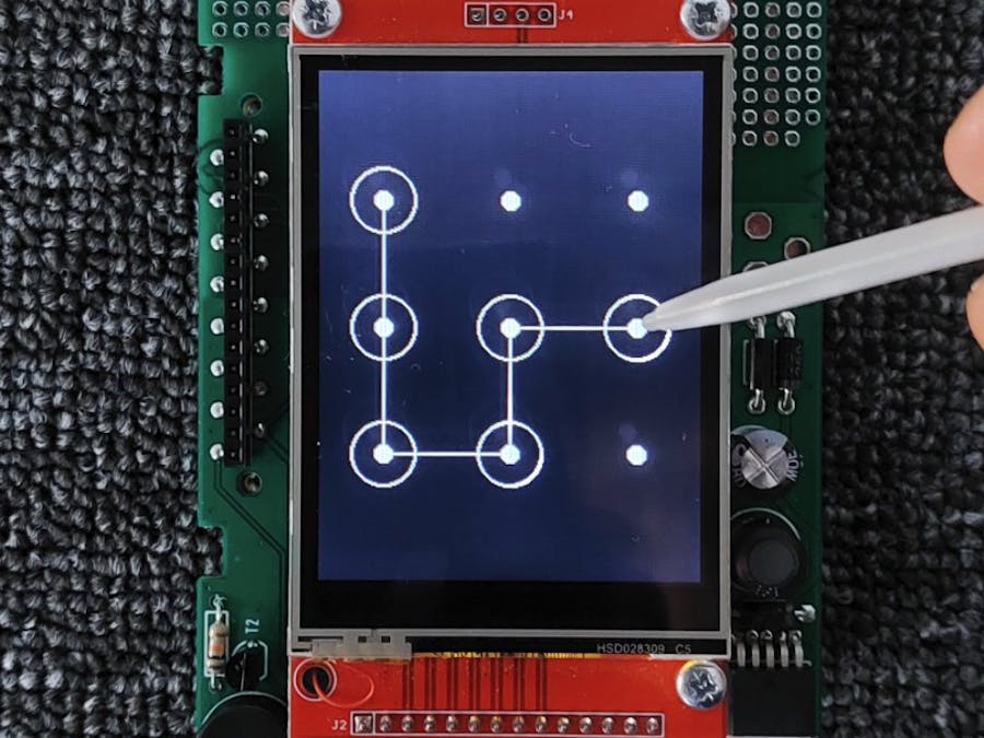
Most people are familiar with pattern lock entries from their smart phone, e.g. for unlocking the phone. Such an unlocking algorithm can also be very useful in small embedded projects, e.g. to open doors or to protect parts of a graphical user interface from unauthorized access.
HardwareI use an AZ-Touch kit for my code, which are small 2.8" touchscreens in a wall-mounted housing. These kits contain an ili9341 touchscreen and a circuit board onto which a microcontroller board can be plugged. The AZ-Touch are available for different platforms e.g. Feather boards or Arduino MKR. The AZ-Touch usually comes as a (partially assembled kit), in which some components still have to be soldered on.
Of course, you can also use a simple Ili9341 display and connect it to the corresponding microcontroller board with jumper wires. The circuit diagram of the AZ-Touch Feather kit can serve as a reference - see appendix.
Additional LibrariesIn order to be able to compile the program in the Arduino IDE, some additional libraries are required, which must be loaded beforehand via the library manager:
- Adafruit GFX Library
- Adafruit ILI9341
- Paul Stoffregen XPT2046 Touchscreen Arduino Library
At the moment the code does not yet support learning mode. However, this can easily be retrofitted if required. The "correct" pattern still has to be defined manually in the current code. An array with a maximum of 15 points is defined for this purpose.
The code already contains some example patterns.
L - pattern:
#define pattern_OK (int[]){1, 4, 7, 8, 9, 0, 0, 0, 0, 0, 0, 0, 0, 0, 0,}M - pattern:
#define pattern_OK (int[]){7, 4, 1, 5, 3, 6, 9, 0, 0, 0, 0, 0, 0, 0, 0,}You can easily create your own pattern. Each point on the screen is assigned a number. All you have to do is arrange the numbers in the corresponding order in an array.
The program already supports various microcontroller boards. In addition to some Feather boards, Arduino MKR and ESP32 DEV KITC are also supported. The corresponding GPIO pin assignments are stored in the pin_definitions.h file. The respective board is automatically recognized according to the settings in the Arduino IDE via preprocessor definitions. If your board is not yet included, you can extend the pin_definitions.h file accordingly.
Using the demoInitially, only the dot grid is displayed. Now you can press the screen at any point and then move the pen or finger to the next points. Each detected connection is represented by a white line.
If the pattern matches, a corresponding screen is displayed and an acoustic confirmation tone is emitted.


Comments
Please log in or sign up to comment.