In September, 2015, my 8 year-old garage door controller finally had enough coffee spilled on it and gave way. It was time for me to go shopping for a replacement, this is where my journey begins.
I recall scrolling through page after page of Amazon.com and eBay.com looking for the brand and model. While I was aware that a generic, “universal” type could be used, my OCD was on high alert and would not allow me to settle on something that didn’t match its’ “twin” controller in my wife’s car.
A short time later, I’m satisfied with the $35.00 replacement I found and quickly navigated to the checkout page. It was on that page that a “last minute offer” piqued my interest and my life had changed...for the better.
The offer was for an Arduino microprocessor, something I had briefly read about but had no working knowledge of what it really was. By the time I went to sleep that night, I was so intrigued and thus began my journey into microprocessors, my Internet of Things (IoT) and the project you’re about to read.
Before I get into the nuts and bolts of the project, I want to disclaim that I’m not an engineer, not a computer programmer and I still confuse AC and DC power on a voltage meter. You see, I’m an end user of electronics. I like plug & play. If it doesn’t work, it’s not me, it’s the product. I share this with you for a couple of reasons: (A) If I can make this project, so can you. In seven months, I’ve gone from zero knowledge in microprocessors, software and electronics to working on a couple dozen projects. These are being built on Raspberry Pi’s, Arduino’s, Particle Photon’s, Spark Core’s, etc. This IoT thing is big and it’s not ever going to stop. The two main ingredients are a little knowledge and a lot of creativity....if you can think it, you can build it! (B) The IoT community is amazing. If not for all the free education I’ve received from fellow “hackers”, I’d be lost and wouldn’t be writing this project. An amazing group of people are available in forums, chat rooms and Youtube to answer your questions and help you figure it all out. You’ll find the term “pay it forward” is quite actionable in this community.
Without further delay, let’s get on with my first published, IoT project!
Project Scope & Core DeliverablesIn the spirit of IoT, more specifically, home automation, I wanted a garage door that was a complete solution. At a minimum, the Project Scope would meet or exceed the following Core Deliverables:
A) Remove the need for an additional gadget in my vehicle - aka my garage door remote. No more worrying about relying on batteries or general operation.
B) Utilize existing technology that I carry with me wherever I go....my phone.
C) Provide “global” access so it could be operated anywhere if needed. If I want to allow access for a friend or family member, I’m able operate it from anywhere in the world.
D) Monitor the status of the garage door. Is the garage open? Closed? Did the power outage disrupt the relay?
E) Easy to “transfer” the technology to others. By providing the apps, code and user login information, the ‘virtual controller’ could be given to another person by way of a few apps or code.
F) No additional websites, ongoing charges, hosting fees, etc. are required to operate any portion of this project. An app or two to operate the garage (if needed) is ok but I don’t want to access a separate webpage.
G) No Bluetooth needed. While I like BT, I don’t want to worry about being “in range” and wait for a connection.
H) No need to be on my local network to operate. I do not want to wait for a connection, therefore, this should be accessible via 3G/LTE in addition to WiFi.
I) Integrate with other home-automated projects easily and seamlessly, regardless of the platform. Ideally, I’ll be able to access all home automation modules through one screen, centrally located in the house (maybe the Raspberry Pi 7” TFT display)
Resources (non-hardware)A) Particle Community Forum - Particle Community Forum that provided an amazing resource for me to complete my software coding. To start with zero knowledge about coding and end up with where I’m at today says a lot about this forum.
B) Make: Getting Started with the Photon by Simon Monk - This is a terrific book that Simon Monk (the Godfather of Arduino’s et al) put together. While the Internet provides up to date and quick to find information, nothing beats having a physical book in front of you to read and reference.
C) Fritzing - Fritzing - Great website/software that allows you to map out your project on a virtual breadboard. It’s free and very easy to use.
D) Dallas Makerspace - If you have a local Makerspace in your area, I highly recommend joining. Not only are the tools and resources available, people are really smart and eager to help! Dallas Makerspace
Resources (hardware & tools)**Photos below
* (1) Spark Core or Particle Photon Particle - this remarkable MCU can be programmed via an iOS/Android app for simple pin assignments or for more detailed coding, the Particle online IDE (very simple to use and a great community of others to assist).
* (1) Magnetic Reed Switch Magnetic Reed Switch(can be wired NO (Normally Opened) or NC (Normally Closed). Used as a sensor so that I’m able to monitor the garage at all times as to the status. OPTIONAL (I originally included this in my original plans but opted to go with the visual confirmation and use a camera)
* (1) 4-Channel Spark Core Relay Board or 2-channel 5V Relay Module 5V Relay Module/Board. For my project and this Instructables is based on the Spark branded relay board. However, any 5V module will work with a few changes in the wiring.
* (1) Small Breadboard
* Wire - about 10-15 feet of solid core wire - two different colors
* Power - depending on your connection, either a USB or small wall wort would work. In this project, I’m using a standard 7V wall wort to power the board/unit.
* A case that can fit your project. I designed a 3D printed case specifically for the project. - OPTIONAL (but makes it look great and provides protection)
Prerequisites & Disclaimers
- This tutorial covers mainly the hardware and wiring used for a Hands-Free Garage Door and limited software setup. Please refer to the setup and installation of the Spark Core/Particle Photon and any apps that are discussed.
- This project involves high voltage electricity. Please be sure to disconnect all electricity prior to the install. Better safe than sorry!
Step 1 - Build the Relay Shield Box “Relay Box”
Objective: Here, you’ll prepare the Particle Relay Shield by installing the Spark/Photon, REED SWITCH* (if you want to have one) and determine the relays you’ll use
*The REED SWITCH is optional. Having one on your project will allow you to determine if your garage door is open or closed by sending back a feedback response. It’s important to note that while my project includes both the hardware and code for a REED SWITCH, I prefer not to rely on it, I now use an old iPhone with a 24 hour/365 day stream (free).
Items needed: (1) Particle Relay Shield, (1) Spark Core/Particle Photon (2) Strands of solid core wire - about 4-5 feet each (red and white) (1) REED SWITCH, (as needed) hot glue
- If you have printed up a case for your Relay Shield, secure it accordingly but leave the top off until later. You’ll still need to access the green/black relays.
- Affix the Spark Core/Particle Photon onto the Relay Shield by pressing it onto the outlined headers
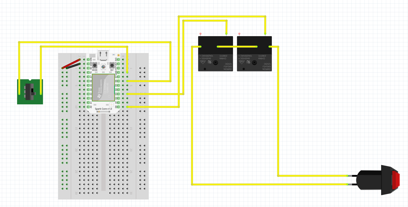
- IF YOU WANT TO INCLUDE A REED SWITCH: Take a strand of the 4-5 foot wire and connect from NC (normally closed) to a pin on the Spark/Photon (I used pin D6). Then, take the other 4-5 foot wire and twist it with the first. You’ll go from COM (common) on the REED SWITCH to GND on the Spark/Photon. Refer to pictures below.
Step 2 - Connecting the Garage Door Motor
Objective: In this step, you’ll connect your “Particle Box” to the garage door motor.
Items needed: (1) Particle Box (assembled), (2) Strands of solid core wire - about 4-5 feet
- DISCONNECT POWER FIRST - no need to fry yourself before you begin
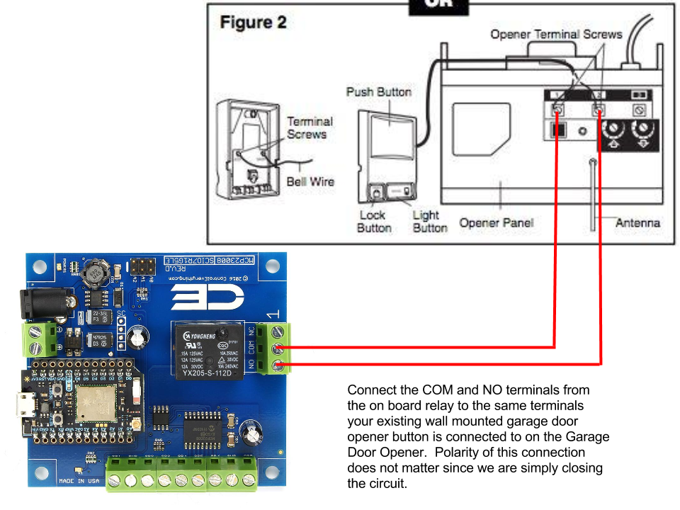
- Your garage motor will have several wires in the back. You’ll need to determine which two wires operate the unit from your wall button. I’ve included a photo of a mock up circuit prior to my install below.
- For mine (LiftMaster), there is a “box” of holes (1 red, 2 white and 1 grey), directly underneath are orange “access button”.
- The first box (red wire) and the second box (white wire) were the two wires that operated the garage door (open or close). In essence, these will also be the wires coming from the wall button that you press to operate.
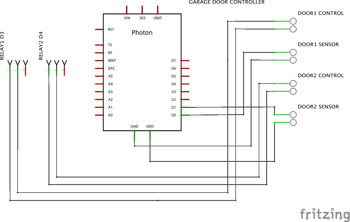
- Now that you’ve located these two wires, you’ve determined where you will input from the Relay Port (green/black box) on the Shield. There are 4 Relay Ports on the Shield, numbered 1, 2, 3 & 4 and each corresponds with a “D”pin on the Spark/Photon. Relay 1 = D0, Relay 2 = D1, Relay 3 = D2 & Relay 4 = D3 (please refer to your manual for the Relay Shield for more details).
- Take each strand of wire (2) and feed the red (hot) into the NO (normally closed) and red (common) into the COM.
- After connecting the two wires onto your Relay Box, complete the circuit by connecting the red/white wires into your garage motor. You may twist them along the way to make it clean.
- Cover your Relay Box, you’re almost done!
STATUS CHECK: At this point, you should have a red/white coming out of the side that are connected to a REED SWITCH on the end. Two other red/white wires are coming out of the green/black relay on the shield and are connected to your garage door motor (red=hot & white=ground).
Step 3 - Provide Power Source/Location
Objective: You’ll provide a steady and safe means of electricity to the 7v power unit on the Relay Shield.
Items needed: (1) Power Strip
- You will need a proper power supply for the Relay Shield that will power the Particle/Spark. This should be near the garage door motor and connected via the power strip. A 7v power supply will be enough to power everything.
- I highly recommend a reputable power strip with shutoff features. Not only will this provide protection in the case of a power outage/surge but it also provides a constant power current. Remember, this involves access to your home, your kingdom, your domain! Don’t mess around by trying to save a few bucks for quality!
STATUS CHECK: At this point, you should have the following completed:
- Relay Box with a REED SWITCH coming out the side - red wire goes to D?, white wire goes to GND on the Spark/Photon.
- Two wires (red/white) coming from the Relay Shield (green & black box) - NO and COM going to your garage door motor
Step 4 (optional) - Secure REED SWITCH
Objective: If you want include a REED SWITCH in your project, you’re already wired for one and you’ll just need to hook it up.
Items Needed: (1) REED SWITCH
- Coming from the Relay Box, you have one end of the REED SWITCH already coming out.
- You’ll need to determine a location on the garage door that can be secured to “connect” the switch.
- Refer to the photos and remember, if the two pieces are not “connected”, the garage should be OPEN. This can be adjusted in your code.
Step 5 - Apps, Software, etc... (almost done!)
- Presence - My project uses a visual, live feed (24/7/365) through an old iPhone 4 and a free iOS app called “Presence”. If you go this route, simply download, install and follow the instructions to setup
- If This Then That (IFTTT) - Download this app in your store and install. After setting this up on your phone, you’ll build a recipe to your Spark/Photon as a trigger. If setup using the code I provided, you’ll have two options: (1) ‘relay’ on “xxxxx” & (2) 'status' on “xxxxx” (xxxxx = whatever you named your Spark/Photon). My recipe has a Trigger based on proximity and an Action using ‘relay’. You’ll setup two recipes using these parameters, one for leaving and one for coming home.
- DO Button - Download this app in your store and install. I built the recipe using the Action ‘relay’ and when pressed, it operates my garage door. Think of this as your “override” or old garage door controller.
- Amazon Echo - If you have the Amazon Echo, recent updates have made it remarkably easy to add custom voice commands. Simply go to the Alexa settings and follow the instructions to “trigger a custom command”. You will see in this setup where the Echo asks for the Spark/Photon credentials. This was probably the easiest part of the entire project.
For a quick video overview, please visit my Youtube posting.
https://youtu.be/_1nhsPPXGcU
Final Thoughts & Observations- Since this was both my first real microprocessor project and Hackster.io tutorial, I may have overlooked or confused someone. Please let me know if you have any suggestions or questions and I’ll be sure to answer and update.
- I have had this installed for about 6 weeks now and have not had ANY issues with the setup. We’ve had our share of power surges, outages, etc. and as soon as power is back, it comes back on-line quickly. I’m so confident in this setup that I no longer keep the backup controller in my car. I rarely even double check the garage door via video since it has a 0% failure rate at this point.


Comments
Please log in or sign up to comment.