I needed to read out a Dylos DC1700 Air Monitor, and send the results via wifi to a server for storage and graphing. The Dylos has an RS232 interface. I chose a Huzzah Feather ESP8266 with MAX3232 board. But then could not find a direct example of how to implement things. It is easy when you know how; here is how.
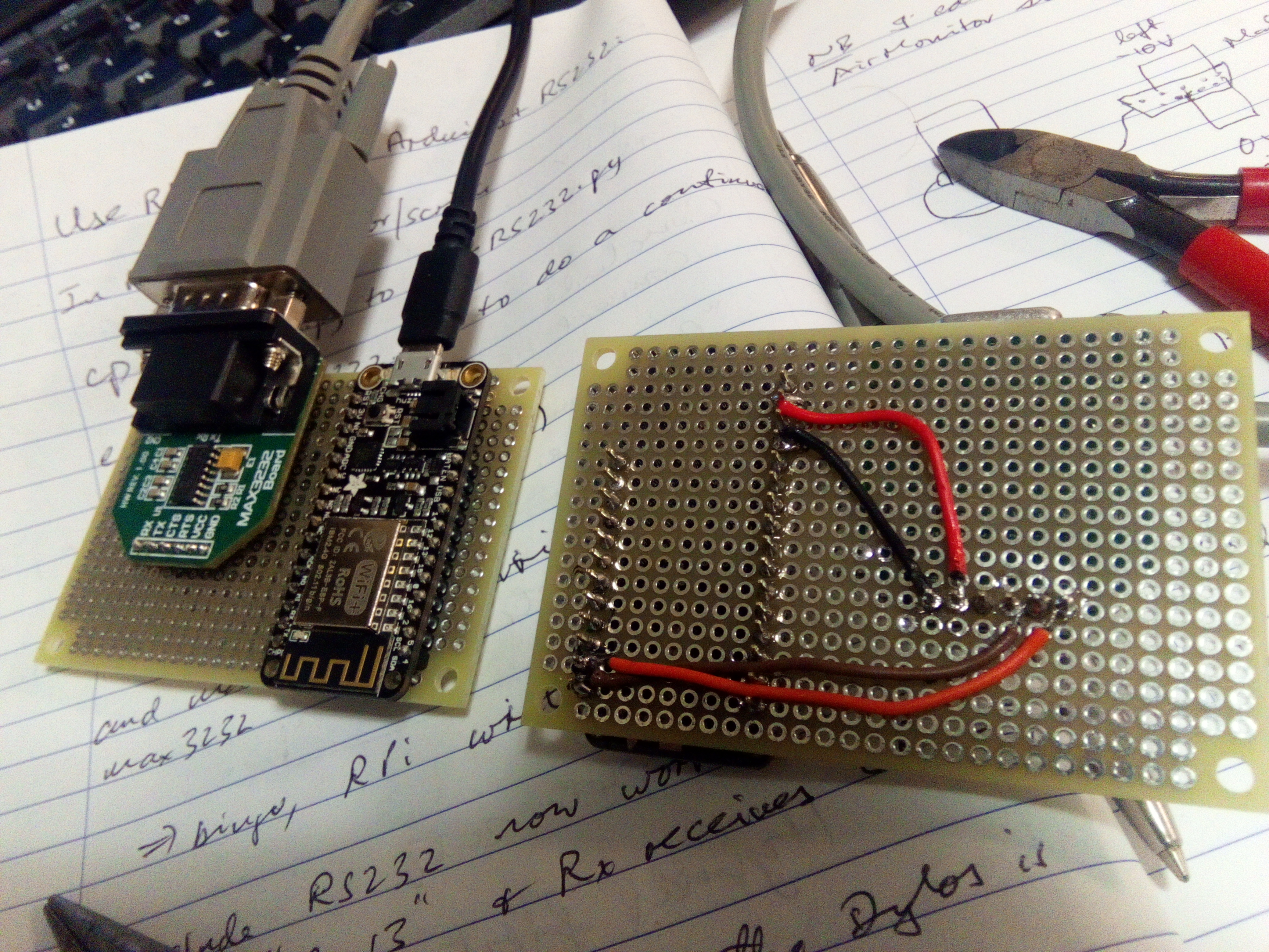
I soldered both components to the board, with USB and RS232 connectors facing the same way, for easy access once placed in a box.
The ESP8266 has only one UART, needed for the USB connector. Don't try using the Rx and Tx labelled pins on the ESP8266 board! That will mess with the USB port connection. Instead, you have to use two digital I/O pins and a "SoftwareSerial" driver. I chose Tx on pin 4, Rx on pin 5. If you change the software, you can use any of the pins labelled with numbers as far as I know. But 4 and 5 seem to not be used for other purposes, so semmed a good choice.
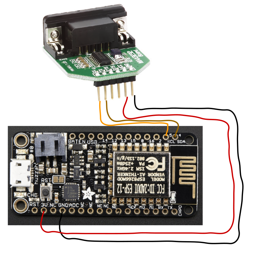
I soldered wires between the boards, as in the pictures. For the communications, Pin 4 on the Feather to Tx on the MAX3232 board; pin 5 to Rx. For power, 3V to VCC and GND to GND. Pretty simple.
Connecting to the Dylos was harder than expected. The MAX3232 pins are swapped: Rx is in the DB9 Tx position, and Tx is in the DB9 Rx position. I suppose they do this so you can use a straight-through DB9 cable. Unfortunately the Dylos is also swapped; so I had to make a DB9 male to DB9 female box in which all lines go straight through except Rx goes to Tx, Tx goes to Rx (a "Null Modem Cable"). Three wrongs make a right, I heard.


Comments
Please log in or sign up to comment.