We bought some land and the intention is to focus on permaculture and automation to develop and maintain an ecosystem where we take from the land as little as possible and add to it as little as possible.
We're using Arduino to automate and improve the efficiency of some of our regular chores and, living 16 miles away from our land, there is great value in automating such tasks from a personal time saving to positive environmental impacts; more automation means less petrol used to travel the 16 miles to carry out relatively mundane tasks.
Our land is set at a 15 degree incline (estimate) descending East to West; this is important to note for another project involving solar panels but we will come to another time!
We want to develop an irrigation system across six individual octants of our land, the final two octantsare dedicated to beehives and chicken keeping. First, we must develop a unit that will measure moisture in the soil and that is what this project does. It measures the moisture level using a single capacitive moisture sensor - in the final design, there will be six sensors.
The end product will be several water butts placed at the top of the incline fitted with hoses that lead to the octant they are intended for and finish connected to an equal number of water butts at the bottom of the incline (to prevent water being wasted by catching overflow). These hoses will be attached using solenoid valves that are fitted to the Arduino unit I am currently developing.
This project is the foundation of the end goal. The capacitive moisture sensors will determine when a charge is sent to the solenoid valves so that it opens allowing gravity to pull the water downwards to the relevant octant; let's say Octant 1 should maintain a moisture level of 40%, we could use an 'if' statement to activate the hose if the moisture level drops below 40% until the moisture level registers at 40% when the charge would cease, closing the valve.
We could easily do this project without the need for the LCD screen, and indeed that was where I had the biggest challenge (you can see the challenge I had by visiting this forum post: https://forum.arduino.cc/t/lcd-print-function-not-working-in-loop-but-works-in-setup/916484/4 - it was so frustrating because I couldn't get anything to print except that expressed in the void setup() section!
You can probably tell I'm quite new to Arduino, having dabbled in other electronics hobbies, I am still very much a beginner in all aspects, make no mistake! That's why I'm publishing this project as I go along because I feel that, first, I have taken from the community of makers (and my pals who are more experienced than me. Big up Edward! Without whom I'd have never even looked at programming) and it is only right to give back and second, because it will help others (hopefully) avoid the same issues I had!
I don't pretend to understand why all the code works. Much of it is an amalgamation of a couple of different projects (see contributors). But without further ado, let's get cracking.
InstructionsFirst, you need to check out the "Hello World" example to really get to grips with the setup because that's what forms the foundation of this project. Part of the set-up includes a potentiometer which I found to be quite redundant but it is included nonetheless.
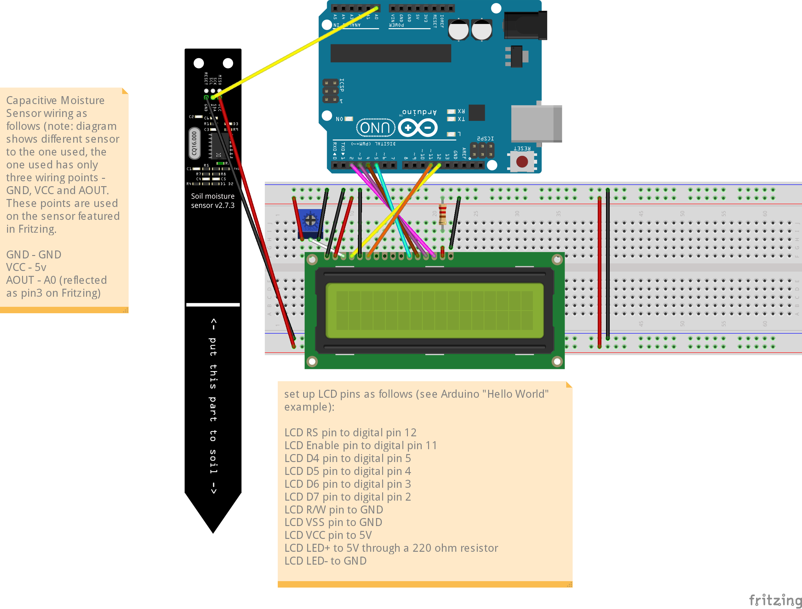
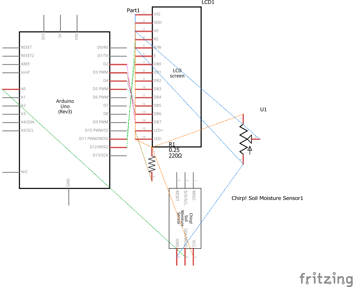
Once you've got your hardware, you need to set up the LCD screen and connect it to your Arduino by attaching the following pins to the corresponding pins on the Arduino. For pins going to ground or power, attach them to the power rails on the breadboard and connect these to the 5v and GND pins on the Arduino.
You should set up LCD pins as follows (these are taken from the Arduino "Hello World" example):
- LCD RS pin to digital pin 12
- LCD Enable pin to digital pin 11
- LCD D4 pin to digital pin 5
- LCD D5 pin to digital pin 4
- LCD D6 pin to digital pin 3
- LCD D7 pin to digital pin 2
- LCD R/W pin to GND
- LCD VSS pin to GND
- LCD VCC pin to 5V
- LCD LED+ to 5V through a 220 ohm resistor
- LCD LED- to GND
The VO pin on the LCD screen adjusts contrast and can be connected to the middle pin of the potentiometer; it's really just a gimmick - if it controlled brightness then it would have been far more useful from a power conservation perspective; you could probably run the LCD+ and LCD- through the potentiometer but I've not checked - don't forget, I'm still a novice! Alternatively, you can probably just skip the VO pin and leave the potentiometer out but as we're following the Hello World wiring for the LCD, I decided to leave it in.
Next, you need to wire the capacitive moisture sensor. The one shown on the breadboard diagram is different to the one I used; Fritzing doesn't offer the same one as I have which features three pins instead of six. Nonetheless, the functionality is the same across the pins used.
Wire the capacitive moisture sensor as follows:
- GND to GND
- VCC to 5v
- AOUT to A0
A quick note on the analogue and digital pins; it doesn't really matter which pins you use provided you adjust the code to suit the pins you choose to use. For this project, the instructions naturally coincide with the code but feel free to play around with it! For example, I use A0 with this capacitor but as I increase the number of capacitors I use, I'll need to use A1, A2 and so on and I will add code blocks using copy paste and just editing the code to reflect the relevant pins used.
Now that you've wired up the LCD screen and moisture sensor, you're ready to hook it up to your PC, open your Arduino IDE and copy the code over ready to install. You might find, upon attempting to install, that the library isn't installed for the LCD screen and if that is the case, you'll need to follow the instructions found here: https://www.arduino.cc/en/Reference/LiquidCrystal
TestingNow you've uploaded the instructions to the device, you should see the moisture level output as a percentage. Go ahead and test it by holding your hand around the entire sensor. You should see it peak at around 100% to 107%. If you submerge it in a glass of water, the rating will show as around 130% (don't submerge the electronic components at the top of the sensor, mind you, as these will corrode and likely fail. To make these waterproof, you'll need some heat shrink tubing or similar that you can use to protect the components). I'm not sure why the rating goes off the scale like this, perhaps it is because the maximum integer is exceeded relative to the percentage scale (between 0% and 100%) - unfortunately, it is beyond my knowledge and understanding to explain why that is. If anyone would like to offer a fix, I will update the project accordingly.


_ztBMuBhMHo.jpg?auto=compress%2Cformat&w=48&h=48&fit=fill&bg=ffffff)


_3u05Tpwasz.png?auto=compress%2Cformat&w=40&h=40&fit=fillmax&bg=fff&dpr=2)
Comments
Please log in or sign up to comment.