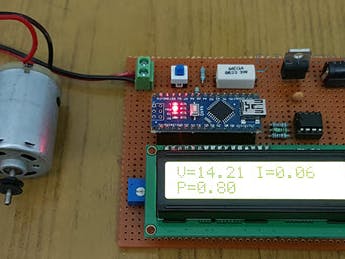
Building your own meters not only carries down the cost of testing but also provides us room to facilitate the process of testing.
Working of the Project:
From the sensor part, there are two sections that are reliable for measuring voltage and current. For measuring the voltage, a voltage divider circuit is executed using a 10KΩ and a 2.2KΩ Resistor.
With the help of these resistors, you can easily measure voltages up to 24V. These resistors also support us in taking the voltage range to 0V – 5V, which is the normal range on which Arduino works.
In order to measure the current, we have to change the current values to conventional voltage values. As per Ohm’s Law, the voltage drop across a load is proportional to the current. Hence, a small shunt resistor is arranged with respect to the load. By estimating the voltage across this resistor, we can calculate the current.
We have used LM358 Op-Amp in Non-Inverting Amplifier Mode to magnify the values provided to Arduino. The voltage divider network for the feedback control includes a20KΩ Resistor and 1KΩ Resistor. These resistors offer a gain of approximately 21.
After Implementation Arduino Wattmeter
To learn more about such IoT Devices, IoT Traning Online is the better way to learn.


_ztBMuBhMHo.jpg?auto=compress%2Cformat&w=48&h=48&fit=fill&bg=ffffff)


Comments
Please log in or sign up to comment.