This project utilized components I received from ON Semiconductor and the Hackster community. Thank you for your trust and support for working on projects.
This project was designed to facilitate the control of the specifications of the environment in which we live. Its basic task is to use graphs to show and compare values outside the home/office (outdoor) and in the home/office (indoor). The values compared in this case are temperature, humidity, pressure, air quality, etc.
The system is divided into three basic parts:
- Hardware (RSL10-SENSE-DB-GEVK and Raspberry Pi Zero W with sensors)
- Cloud (The place where data is downloaded, stored and processed)
- Dashboard (Displays values on a specific website that can be opened on any browser and any device)
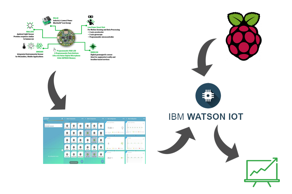
First, let's show the communication between the individual parts.
From the picture we can see that RSL10-SENSE-DB-GEVK communicates with a mobile application RSL10 Sense and Control made by the tile manufacturer using the BLE module from the tile. Application sends data to the configured cloud service (IBM CLOUD => IBM WATSON IOT service) via wireless communication. The user chooses this information voluntarily. This will be shown later.
On the other hand, sensors for temperature and humidity (DHT22), Gas sensor (MQ-2) and Alcohol sensor (MQ-3) are connected to the Raspberry Pi Zero W. Raspberry Pi Zero W via wireless communication sending data to cloud service (IBM CLOUD => IBM WATSON IOT service).
Once the data is stored on IBM WATSON IOT service, then a Dashboard can be formed on their site to be used to monitor the data that has been collected. In this way the connection and communication of this system is realized.
The following nextsteps explain in detail how to create this system.
Step 1: RSL10-SENSE-DB-GEVK connect with application (indoor device)You need to download the application for your mobile device and then start it after installation. Link for download RSL10-SENSE-DB-GEVK application Android.
- You must insert the battery into RSL10-SENSE-DB-GEVK device before running the application.
- After insert battery, device is ready to connect. Turn on bluetooth on your mobile device and launch the app.
- Select your RSL device
- Select parameters for read from RSL device
- You will see data on display in application.
Next photo is realisation in application for last tree steps.
- First, you must creating accont on IBM Cloud page. This steps is very easy for all of us and I will skip this steps.
- Next step is: Go to IBM Watson IoT page and lounch this service for first time (Photo bellow).
This will launch the Service and take you to the IBM Watson IoT Platform page. Click on Browse Devices in left menu.
- Click on Add Device (top right corner)
- Insert your Device Type and Device ID for RSL device and on Security tab insert Auth. Token.
- On Summary tab click Done.
- Go to APP tab in left menu and click Generate API Key in top right corner. Insert description in frist tab, click Next, select Role and click Generate Key. Next page is details for your API Key.
Having created the IBM Watson IoT Service, we now need to connect that service to an android application. To connect an application to an IBM service, you need to retrieve the following information from "Step 2":
- IBM client name: Any text string
- App ID: Enter the API Key (generated in step 2)
- IBM Client ID: Skip this field. (Auto populated as per the entry in App ID field
- Device Type: MApp (as per step 2)
- Device ID: The Device ID created on the IBM cloud (as per step 2)
- Protocol : Choose TCP or SSL
- URL:.messaging.internetofthings.ibmcloud.com (replace with your organization ID as per step 2)
- Port No: 1883
- Username: Enter the API Key (generated in step 2)
- Password: Enter the Authentication Token (generated in step 2)
- Leave “Supports MQTT v3.1.1” & “SSL Certificate” boxes unchecked
Next photos show how to set up an IBM service and enter the information listed above.
The photos detail how to do the steps, the name of the photo specifically states what needs to be done at a given point.
After the in-app data is sent to the IBM cloud service. The dashboard on which the data will be displayed needs to be enabled.
Step 4: IBM Watson IoT DashboardSelect Board (first icon) from the left menu, then increase "Create New Board". Then the window will open as next photo.
Insert Board name and Description (optional). Click Next and save your new board.
Click on your board and in top right corner click on Add New Card button. After that, pop-up will be open. This pop-up is look like as next photo.
In this pop-up, select the device from which you want to view the data. (This is important when creating another part that reads data outside the home / office - the Raspberry Pi). Click Next.
The pictures below show how, after selecting the device from which the data is being read, further select which data we want to display on the card. There is also an assignment of the name, unit of measure and color that we want to assign to this card.
After creating all the data cards from the RSL Board, the layout of the dashboard is shown below:
In order to have the device out there, we need to connect the sensors to the raspberry pi board. The sensors used are:
- DHT22 - temperature and humidity sensor
- MQ-2 - Air quality sensor
- MQ-3 - Alcohol sensor
The sensors, as already mentioned, connect to the Raspberry Pi tile on which the Raspbian system is installed, and code running on the tile is stored on the desktop. The code is written in Python programming language.
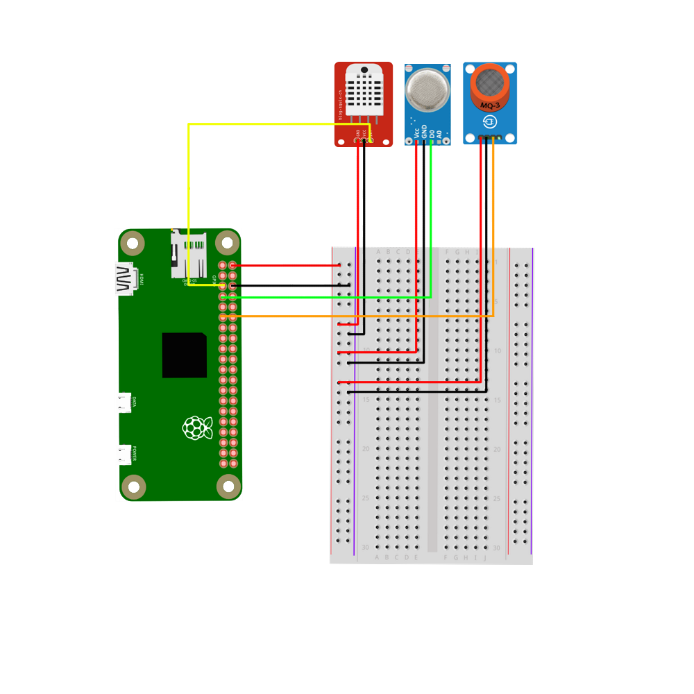
Scheme for connecting sensors to Raspberry pi is in attacments.
Step 5.1: How to install Raspbian on Raspberry Pi?- Get started, download the .img file on the Raspbian system. Download it from this link.
- After you download the system image, now you need to boot your SD card, i.e. to mount the image you downloaded to an SD card. Etcher is a graphical SD card writing tool recommended by Raspberry pi community.
- Download Etcher and install it.
- Connect an SD card reader with the SD card inside.
- Open Etcher and select from your hard drive the Raspberry Pi .img file you wish to write to the SD card.
- Select the SD card you wish to write your image to.
- Review your selections and click 'Flash!' to begin writing data to the SD card.
Executing the previous steps on your SD card is set by the Raspbian system. Let's move on.
- Now connect the display (HDMI), mouse and keyboard (USB) to Raspberry Pi Zero W. Connect power and you can start working. (username: pi and password: raspberry)
(If you have one, do not take the following steps)
- If you don't have a monitor, keyboard, and mouse, then use the linux terminal on your computer. After mounting an image, make two text files on your MicroSD card.
- With the name "ssh" empty and without extension.
- Under the name "wpa_supplicant.conf" and enter this code in file:
ctrl_interface=DIR=/var/run/wpa_supplicant
GROUP=netdev update_config=1
country=US
network={
    ssid="YOURSSID"
    psk="YOURPASSWORD"
    scan_ssid=1
}
Replace YOURSSID and YOURPASSWORD with whatever is used for your network setup. - Now after you insert the card into Raspberry Pi and connect it to power, it will connect to the network.
- In the terminal of your computer, run this command:
ssh pi@<IP>(username: pi and password: raspberry)
<IP> is IP address of your Raspberry Pi. (You can find the IP addresses by scanning ip addresses on your network).
- This is necessary because each time when connecting Raspberry Pi to the power supply, the script will automatically start. It's simpler because we will not have to run the script again in the terminal every time.
- This resolved the user's frustration, user won't have to run script every time when the power supply falls. Now, user must only provide new power, everything else will happens in the background.
- Let's start with the setting. Run next command in terminal on Raspberry Pi:
sudo crontab -eChoose editor and enter the next line of code at the end of document:
@reboot python3 /home/pi/Desktop/script_name.py/home/pi/Desktop/script_name.py is path to the script you want to run.
- Reboot Raspberry Pi.
- Now, when you start the Raspberry Pi, the script you selected will automatically launch.
Libraries are needed to read data from the DHT22 sensor and library for IBM Watson IoT Service. This sensor are included in project, therefore libraries need to be installed.
The installation of the DHT22 library is performed by running next commands in terminal:
git clone https://github.com/adafruit/Adafruit_Python_DHT.git
cd Adafruit_Python_DHT
sudo python3 setup.py install
The installation of the IBM Watson IoT Service library is performed by running next commands in terminal:
sudo apt-get update
sudo apt-get install python-dev python-pip
sudo pip install wiotp-sdk psutil
wget https://github.com/ibm-watson-iot/iot-python/archive/master.zip
unzip master.zip
cd iot-python-master/samples/psutil/src
Connecting to Quickstart allows you to quickly verify your installation and connectivity to IBM Watson IoT Platform. The –quickstart
python iotpsutil.py --quickstartThe following data points are collected:
- CPU utilization (%)
- Memory utilization (%)
- Outbound network utilization across all network interfaces (KB/s)
- Inbound network utilization across all network interfaces (KB/s)
Use the URL provided to launch the Quickstart web application and see the events coming from your Raspberry Pi visualized in real time.
Step 5.4: Python code for reading and sending data to IBM CloudThe code is attached to a project called raspberrypicode.py.
We will comment on the essential lines used to read sensors data.
DHT = 3
MQ2 = 4
MQ3 = 17

GPIO.setmode(GPIO.BCM)
GPIO.setwarnings(False)
GPIO.setup(MQ2, GPIO.IN)
GPIO.setup(MQ3, GPIO.IN)
First three lines define the pins to which the sensors are connected. The following four lines define the pins through which the data on the Raspberry Pi will enter.
h,t = dht.read_retry(dht.DHT22, DHT)
air = GPIO.input(MQ2)
alc = GPIO.input(MQ3)
	data = {
		"tempRPi": t,
		"humidityRPi": h,
		"airRPi": air,
		"alcRPi": alc,
		}
First line of the above code reads data from the DHT22 sensor connected to DHT pin. The following two lines are used to read data from the MQ-2 and MQ-3 sensors.
data is a json format that is send to IBM Watson Service.
Step 6: Connecting Raspberry Pi with IBM Watson Cloud ServiceFor this step, another device needs to be created on the IBM Watson platform. This means that it is necessary to repeat step 2 of this description and create a new device with a new name.
Once created, we will have access to the necessary information used to connect to the platform. We will use environment variables to configure the device client to connect to your instance of Watson IoT Platform as your registered device.
These variables correspond to the device parameters for your registered device:
- WIOTP_IDENTITY_ORGID
- WIOTP_IDENTITY_TYPEID
- WIOTP_IDENTITY_DEVICEID
- WIOTP_AUTH_TOKEN
Enter the following commands in the terminal to connect the Raspberry Pi to the IBM Watson platform:
export WIOTP_IDENTITY_ORGID=yourorgid
export WIOTP_IDENTITY_TYPEID=yourtypeid
export WIOTP_IDENTITY_DEVICEID=yourdeviceid
export WIOTP_AUTH_TOKEN=yourauthtoken
python raspberrypicode.py
yourorgid, yourtypeid, yourdeviceid, yourauthtoken is data that you read from a newly created device on the platform.
After the last line of code is launched (python raspberrypicode.py), the data will be automatically submitted to the IBM Watson platform.
In order for the data from the Raspberry pi tile to be displayed on the dashboard, it is necessary to select new cards on which this data will be selected. The principle is the same as in Step 4.
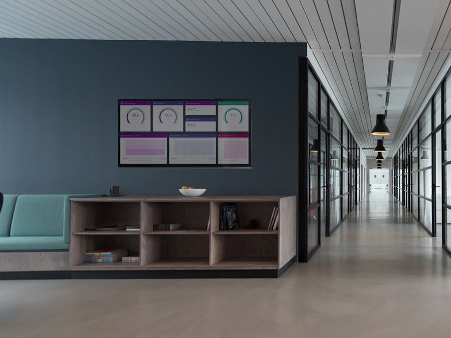
The following photos show the devices used in this project. There's also a dashboard that was created on the IBM Watson Cloud platform and launched on an Android TV device.
As you can see from the attached Raspberry pi with sensors is placed outside the home / office. While the RSL device is in the office, when the user's cell phone is in the home / office, then via BLE communication the data is delivered to the IBM Watson Cloud platform and the user will be able to monitor the parameters outside and inside the home / office on an Android TV device.
Attached is a video showing the functionality of this system.
Thanks for reading my project, good regards everyone.


Comments
Please log in or sign up to comment.