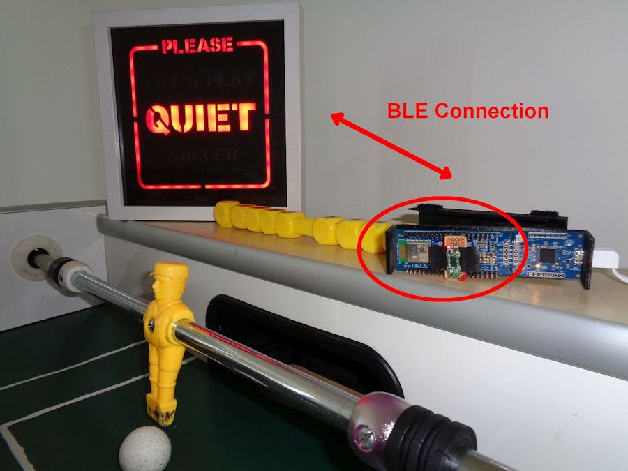
Room planning can become a challenge - at home as well as in a company. And so it may happen, that two rooms will share one wall... although one room is requested to be quiet, while in the other some more action takes place, e.g. parent's bedroom next to the children's room - Or, like the original reason for this project, caused by a building reconstruction the new cafeteria area was next to a meeting room. And worse, in the leisure room there is a table soccer available what basically prevents doing any meeting - but's shouldn't it be vice versa?
The ideaDepending on the meeting room occupancy - detected by PIR or radar sensor - a light panel shall inform and ask people to stay silent or allows playing table soccer when no meeting takes place.
To make the installation easy a wireless communication shall be used.
Infineon's 60GHz radar sensor fits perfect, as it allows to install the sensor discretely behind any front face, while a PIR sensor always is visible unbeautifully in a room by its typical white plastic cupola.
The XENSIV™ BGT60LTR11AIP radar shield runs in an autonomous mode (see also 'Electronic Assembly'), that reduces the effort for implementation. No complex knowledge is required, as two signals directly inform about the detection of a target and optionally the phase (approaching or departing). The latter is not need for the current purpose. Any kind of microcontroller can read in the status of the sensor by at least one or two GPIOs.
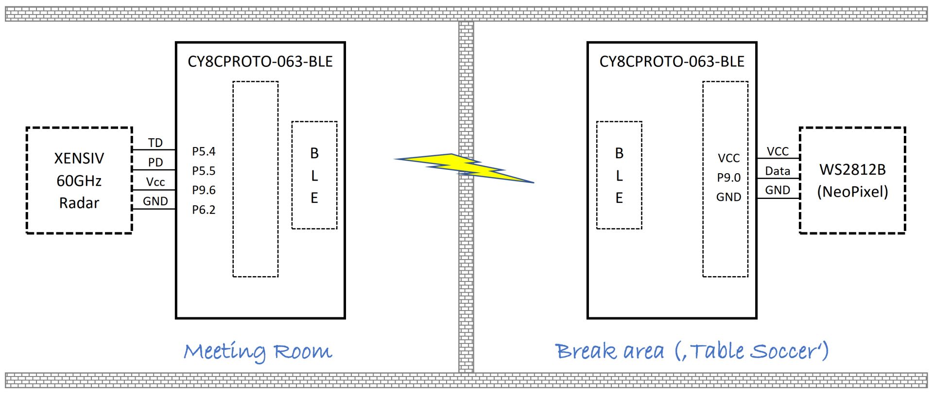
For the communication Bluetooth Low-Energy (BLE) is sufficient, as we just need to bridge one wall and a couple of meters. So decision was made for the CY8CPROTO-063-BLE kit based on the CYBLE-416045-02 that includes onboard crystal oscillators, trace antenna and a royalty-free BLE stack compatible with Bluetooth 5.0.
This kit from Infineon formerly Cypress comes with the KitProg, a programmer and debugger that is very useful while software developing, but can be broken afterwards to reduce board size. In case the kit is still to big, the Bluetooth 5.0 qualified single-mode BLE-module (4mm × 18 mm × 2 mm) can be ordered and used stand alone, too.
Electronic Assembly (Radar System - Meeting Room)As already mentioned the radar sensor shield provides an autonomous operation mode, what needs to be selected by removing R3. Details can be found in AN608 from Infineon.
NOTE: Unfortunately the R3 was chosen from one of the smallest SMD sizes and requires highest concentration and special SMD solder tooling for removing. Be careful!
The radar module has 4 castellated holes that nearly fit between the I/O headers of the microcontroller kit. However, to avoid any damage of the plated holes and to get the mounting more robust, a small bread board PCB is used as intermediate adapter for better fixing as the following picture shows. For better isolation a tape is used.
For the given software the radar module is fit on pins 5.2 and 5.3, as well as 9.4 and 9.5 on the opposite side. The radar signal TD (target detection) will be processed by the software, while the port pins 9.4 (GPIO drive high level) and 9.5 (GPIO drive low level) provide the power supply to the sensor. Using GPIOs for powering the modules simplifies the connection as no manually wiring is needed.
A black 3D printed case has been designed 'to hide' the system.
Electronic Assembly (Light panel - Leisure Room)Assembling the light panel is very simple, as it just uses a WS2812B type based LED stripe. In our case, we drive 62 LEDs ("Let's play Soccer", "Please Quiet"). However, just one output pin is needed (P9.0), so the related pins 9.0, VDD and GND and the rest is handled by the software.
NOTE: The VDD provides only 3.3V voltage supply. Although the WS2812B are specified for 5V, it works fine with the 3.3V, and the brightness is not an issue for the LED panel. Be careful also with respect to the maximum current that is allowed for the on-board AP7365-WG-7 what defines 600mA. Hence I close my eyes for this Maker-project ;-) Happily it works!
SoftwareTwo projects have been setup to develop the firmware of each part. For the Infineon (formerly Cypress) PSoC6 microcontroller the ModusToolbox IDE replaces in future the former PSoC Creator. As Modus is Eclipsed based many developers loves it, but the approach is partly different from the former GUI like design input. However, as the software part is not too complex and straightforward, so do as follows:
- Extract both project zip-files into one local folder what will be the workspace folder, e.g.: c:\myProjects\RemoteRoomRadar\c:\myProjects\RemoteRoomRadar\RemoteRoomRadar-BleAdv-Radarc:\myProjects\RemoteRoomRadar\RemoteRoomRadar-BleScan-LED
- Open ModusToolbox and select the the workspace folder (e.g.: c:\myProjects\RemoteRoomRadar)
- File -> Import... ModusToolbox -> Application Import... e.g.: c:\myProjects\RemoteRoomRadar\RemoteRoomRadar-BleAdv-Radar
- File -> Import... ModusToolbox -> Application Import... e.g.: c:\myProjects\RemoteRoomRadar\RemoteRoomRadar-BleScan-LED
- Click on project RemoteRoomRadar-BleScan-LED
- Open the Library Manager from the Quick Panel and click the Update button. When done, then close.
- Update in same way the RemoteRoomRadar-BleAdv-Radar project
The projects are ready to use and can be build and programmed to the dedicated CY8CKIT-063-BLE.
In the following I will give some hints how to configure both projects in case modification shall be done.
RemoteRoomRadar-BleAdv-Radar (Sender)This project sends BLE advertising packages as when the radar has detected a target.
The pin assignment for radar are done by the Device Configurator -> Pins.Current assignment:
- P5[4] : RADAR_TD
- P5[5] : RADAR_PD
- P6[2] : RADAR_GND
- P9[6] : RADAR_VIN
Use the Bluetooth Configurator to adjust the BLE advertising package. Currently the Device Name 'RoomRadar' with address '00A050-C011AB' is defined. Note: The BLE scanner just uses the given address, without proving the name.
Inside main.c the RADAR_PD pin is polled and activates BLE advertisement accordingly.
for(;;)
{
    if (   ( u32BleAdvOn == 0 )
        && ( (0 == cyhal_gpio_read(RADAR_TD)) || (0 == cyhal_gpio_read(USERBTN)) )
        && ( CY_BLE_ADV_STATE_ADVERTISING != Cy_BLE_GetAdvertisementState() )
       )
    {
        u32BleAdvOn = 1;
        u32TimeDelay = 25;
        Cy_BLE_GAPP_StartAdvertisement
        (CY_BLE_ADVERTISING_FAST, CY_BLE_PERIPHERAL_CONFIGURATION_0_INDEX);
    }
    else
    if (   ( u32BleAdvOn == 1 )
        && ( 1 == cyhal_gpio_read(RADAR_TD) )
        && ( 1 == cyhal_gpio_read(USERBTN) )
       )
    {
        u32BleAdvOn = 0;
        Cy_BLE_GAPP_StopAdvertisement();
    }
} // for(;;)This project scans for advertising packages on air. When it find the given address of the Radar (Sender) then it controls the WS2812B LEDs to display the related message ("Please Quiet") in red, otherwise the green message ("Let's Play Soccer") is shown.
The address of the sender is coded inside main.c
cy_stc_ble_gap_bd_addr_t PeripheralDeviceCollaboratorRoom =
{ {0xAB, 0x11, 0xC0, 0x50, 0xA0, 0x00 } };
Inside the BLE state machine a delay (u32TimeDelay) is set when a matching advertising package is received. This is kind of hysteresis to avoid any flickering of the LED panel caused my interrupted radar detections. The maximum delay is set here to 200 what represents 20 seconds currently.
void BleStackEventHandler(uint32_t event, void *eventParam)
{
    case CY_BLE_EVT_GAPC_SCAN_PROGRESS_RESULT:

    advReport = *( cy_stc_ble_gapc_adv_report_param_t *)eventParam;
    if (AddressCompare(PeripheralDeviceCollaboratorRoom, advReport.peerBdAddr))
    {
        u32TimeDelay = u32TimeDelay + 50;
        if (u32TimeDelay>200)
        {
            u32TimeDelay = 200;
        }
    }

}
Inside the systick timer interrupt service routine the display is refreshed each 100ms accordingly on the value of the delay variable (u32TimeDelay).
void mySystick_ISR()
{
    if (u32TimeDelay)
    {
        u32TimeDelay = u32TimeDelay - 1;
        cyhal_gpio_write(LED_G, 0);
        DisplayPlease(RED);
        DisplayLetsPlay(BLACK);
        DisplayQuiet(RED);
        DisplaySoccer(BLACK);
        DisplayRahmen(RED);
        StripLights_Trigger(1);
    }
    else
    {
        cyhal_gpio_write(LED_G, 1);
        DisplayPlease(BLACK);
        DisplayLetsPlay(GREEN);
        DisplayQuiet(BLACK);
        DisplaySoccer(GREEN);
        DisplayRahmen(GREEN);
        StripLights_Trigger(1);
    }
}
Again, the pin assignment for connection of the LED stripe can be done by the Device Configurator -> Pins. Current assignment:
- P9[0] : WS2812B
In a first test the functionality is tested on a table
before installation of each system to it's intended location.
SummaryBy using CY8CPROTO-063-BLE and the new XENSIV™ BGT60LTR11AIP 60GHz radar sensor quickly an interesting and helpful application could be realized and simple communication was established just by processing pure BLE advertising packets. The system is very open to be adapted to many other scenarios. The big advantage of the radar system against the known PIR sensors is that it can be hidden inside a case that allows also much more beautiful installation (than roughly shown by this example project).
Go ahead and realize your idea! Stay safe!
Holger


_5Wpf9nkOTC.png?auto=compress%2Cformat&w=48&h=48&fit=fill&bg=ffffff)


Comments
Please log in or sign up to comment.