


Hardware components | ||||||
| × | 1 | ||||
Software apps and online services | ||||||
 |
| |||||
 |
| |||||
 |
| |||||
| ||||||
5G is the new and most advanced version of the world’s cellular and wireless systems. 5G networks have started to be launched by AT&T, Verizon, and T-Mobile in the USA and around the world. 5G comes with a new and advanced featured for connecting large number of small devices called Narrowband Internet of Things (NB-IoT). NB-IoT devices connect through the mobile operator tower (known as the base station) to form an application domain called Internet of Things (IoT). These devices can be used to connect devices in the home, in buildings, throughout a city, or in remote areas.
NB-IoT delivers much better capability and performance than Bluetooth or WiFi: increased area coverage of up to one square kilometer, up to 200, 000 devices per a single base station, battery lifetime of up to 10 years, and better coverage for areas with weak signals such as underground garages and elevators.
NB-IoT devices are used in smart homes for lighting, appliances control, smoke and alarm systems, heating and air conditioning, and media and security systems. NB-IoT devices are also used in elder care to monitor medical emergencies such as falls or seizures.
Smart transportation uses NB-IoT devices to control traffic lights, provide parking information, road tolls systems, or for safety, and road assistance. Smart city uses NB-IoT to monitor highway, infrastructure grids such as electricity, gas, or sewage, or for public safety and disaster management.
NB-IoT devices can make farming more controlled and accurate with the use of soil moisture, light, rainfall, humidity, and wind speed sensors, automating irrigation system, or monitoring live stocks.
NB-IoT devices are connected to the mobile operator base station, known as eNodeB. The eNodeB is connected to the core network. Core network contains the mobile operator network servers such as the server that authenticate and authorize the device to use the core network and be able to transmit and receive data through the core network. Authorization and authentication of the device are done by exchanging the data stored on the SIM card inserted into the NB-IoT device. The core network also contains an Access Point (AP) and the device has to specify the Access Point Name (APN) when establishing a connection with the eNodeB. AP provides the NB-IoT device with connectivity to the Internet. The APN is the name of this access point which provides internet connectivity to the NB-IoT device. The APN is a name which follows the same rules of DNS naming convention.
Figure 1 shows one application of NB-IoT in smart buildings and smart metering where NB-IoT devices are connected to the eNodeB and they collect a large amount of data and information and send them to a remote server for processing.
To help makers realize the full potential of 5G, “5G HUB”, a USA-based company, developed an ultra-compact circuit board, called NB Board, that has an NB-IoT and GNSS in a single modem. It features an embedded 32-bit ARM Cortex microcontroller and a cellular NB-IoT modem. The modem provides NB-IoT cellular connectivity in addition to a high-precision GPS location information.
The NB board can be used with the Amazon and Azure clouds, real-time operating systems, and with the Arduino IDE to develop applications using the Arduino programming language. Many examples are shipped with the NB board that illustrate how to program the NB board to be used with networking protocols, sensors, and motors.
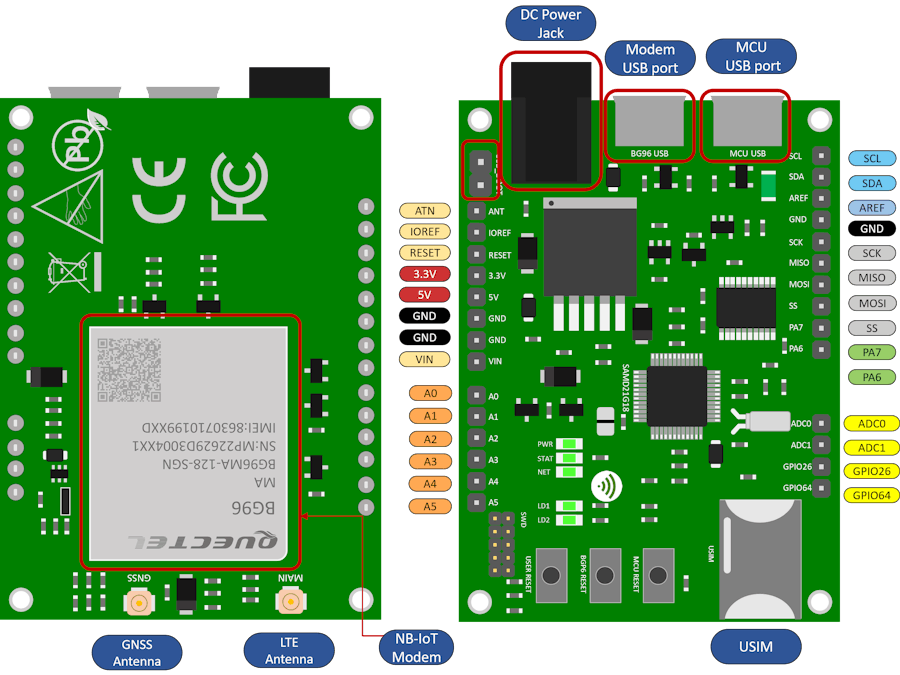
The NB board is shown in Figure 2. It has abundant number of interfaces to connect to sensors, motors, or other electronics devices. The NB board includes analog and digital inputs and outputs, serial interface (SPI, I2C, and UART), analog-to-digital and digital-to-analog converters, pulse-width modulation, a DC power jack, and two USB ports. One USB port used for Arduino IDE and the second USB port used to communicate with the LTE NB-IoT modem directly.The NB board supports rich sets of Internet protocols including TCP, UDP, PPP, SSL, TLS, FTP, HTTP, PING, MQTT, NITZ, SMS. There is also a nano SIM card holder where a SIM card from a mobile operator can be inserted to connect the modem to the cellular network. The modem can connect to either one antenna or one cellular and one GPS antenna.
You need the following two:
1) NB hardware board. It is available from 5G HUB website. The board comes with a USB cable and LTE/GPS integrated antenna. The board can be used with Arduino IDE.
2) SIM card. The Global SIM card covers +150 countries and available at 5G HUB website.
3) Download Arduino sketches, Windows/Linux driver, and other tools from this GitHub repository. Follow instructions to download Windows/Linux drivers and other tools to use.
How to use the NB board with Arduino?Figure 3 show how to setup and connect the NB board to a computer. Insert the Global SIM card into the Nano SIM slot and connect the first USB cable between the NB board and the computer. Through a second USB cable, you can also connect to the LTE NB-IoT modem directly, without use of Arduino, and control the modem. This mode of operation which connects to the LTE modem directly is useful for embedded applications where only LTE modem chip is used thus be able to make small footprints hardware boards.
There is a tool called QCOM tool which is a tool that communicates with the LTE modem directly. The tool is used to send and receive data over the serial port to the LTE modem. You can also use it to send/receive AT commands, data transmission and reception, or GNSS control and NMEA sentences. You can follow instructions on this WiKi to use this QCOM tool to program and send/receive data from the LTE NB-IoT modem. The following screenshot shows a sample of many AT commands exchanged with the LTE modem.
The following screenshot shows how to use the QCOM tool to read GPS data from the NB board.
Through the GPS capability of the LTE NB-IoT modem, you can use it with Google maps. It is interesting to collect GPS Geo-location from the NB board and display it on Google maps.
Using it with Google map, allows to visually view the device tracking information, location, alerts, and reports about all IoT devices being used.
Using the “IoT Connector” Cloud application which uses Google map, you can connect the NB board to Google maps and plots the exact GPS location of the device. In addition, you can create Geo-fencing applications where, for example, you can receive Email or SMS alerts when the device enters or leaves a specific geographical area.
The NB board connect to Google maps, through MQTT (Message Queue Telemetry Transport) protocol which is a secure and light-weight protocol used for IoT devices.
The following screen shoot shows five NB boards whom their GPS-locations are plotted on Google maps.
The NB boards connected through MQTT to an MQTT server which carry the GPS location of the device. The MQTT server calls Google Maps rest APIs to plot the GPS location on the map.You can use the Google map application and follows instructions posted on this web page.
The NB board can be used with a Raspberry PI directly through connecting over the USB ports. Connect the NB board to a Raspberry PI board and follow the following instructions:
1) First run update
sudo apt update && sudo apt upgrade
2) Check Linux version:
root@raspberrypi:/home/pi# uname -a
Linux raspberrypi 5.4.79-v7l+ #1373 SMP Mon Nov 23 13:27:40 GMT 2020 armv7l GNU/Linux
3) Check device driver:
root@raspberrypi:/home/pi# dmesg
[ 12.544039] usb 1-1.4: new high-speed USB device number 3 using xhci_hcd
[ 12.684076] usb 1-1.4: New USB device found, idVendor=2c7c, idProduct=0195, bcdDevice= 3.18
[ 12.684085] usb 1-1.4: New USB device strings: Mfr=1, Product=2, SerialNumber=0
[ 12.684092] usb 1-1.4: Product: Android
[ 12.684099] usb 1-1.4: Manufacturer: Android
[ 12.854908] bcmgenet: Skipping UMAC reset
[ 12.856650] bcmgenet fd580000.ethernet: configuring instance for external RGMII
[ 12.857027] bcmgenet fd580000.ethernet eth0: Link is Down
[ 13.048212] usbcore: registered new interface driver cdc_wdm
[ 13.052479] usbcore: registered new interface driver usbserial_generic
[ 13.052507] usbserial: USB Serial support registered for generic
[ 13.154447] qmi_wwan 1-1.4:1.4: cdc-wdm0: USB WDM device
[ 13.155684] qmi_wwan 1-1.4:1.4 wwan0: register 'qmi_wwan' at usb-0000:01:00.0-1.4, WWAN/QMI device, b2:d6:44:ac:01:a2
[ 13.155853] usbcore: registered new interface driver qmi_wwan
[ 13.165068] usbcore: registered new interface driver option
[ 13.165103] usbserial: USB Serial support registered for GSM modem (1-port)
[ 13.165254] option 1-1.4:1.0: GSM modem (1-port) converter detected
[ 13.166760] usb 1-1.4: GSM modem (1-port) converter now attached to ttyUSB0
[ 13.166920] option 1-1.4:1.1: GSM modem (1-port) converter detected
[ 13.167105] usb 1-1.4: GSM modem (1-port) converter now attached to ttyUSB1
[ 13.167235] option 1-1.4:1.2: GSM modem (1-port) converter detected
[ 13.167405] usb 1-1.4: GSM modem (1-port) converter now attached to ttyUSB2
[ 13.167561] option 1-1.4:1.3: GSM modem (1-port) converter detected
[ 13.167733] usb 1-1.4: GSM modem (1-port) converter now attached to ttyUSB3
4) Check connection:sudo qmicli -d /dev/cdc-wdm0 --dms-get-operating-modesudo qmicli -d /dev/cdc-wdm0 --nas-get-signal-strengthsudo qmicli -d /dev/cdc-wdm0 —nas-get-home-network
5) Change qmi_wwan driver to use Raw-IP.Disable the network interfaces exposed by the cellular module:ip link set dev wwan0 downTrigger the Raw-IP support:echo Y > /sys/class/net/wwan0/qmi/raw_ipEnable the network interfaces again:ip link set dev wwan0 up
6) Activate the data connection in the cellular module:qmicli --device=/dev/cdc-wdm0 --device-open-proxy --wds-start-network="ip-type=4, apn=<YOUR_APN>" --client-no-release-cid
7) Once "Network started" is displayed, you can send a DHCP request on the network interface. udhcpc -q -f -n -i wwan0
8) If the connection was successfully set up established, you now have data connectivity. A ping to a remote server using the cellular network interface can for example prove this:ping -I wwan0 8.8.8.8
• Disconnect the data bearer and data connection over QMI by command bellow and providing the network handle and CID returned at connection activation:qmicli --device=/dev/cdc-wdm0 --device-open-proxy --wds-stop-network=NETWORK_HANDLE —client-cid=CID
Additional useful commands:
Request module manufacturer:
qmicli --device=/dev/cdc-wdm0 --device-open-proxy --dms-get-manufacturer
Get module model:
qmicli --device=/dev/cdc-wdm0 --device-open-proxy --dms-get-model
Get firmware version:
qmicli --device=/dev/cdc-wdm0 --device-open-proxy --dms-get-revision
Get module IDs (IMEI etc.):
qmicli --device=/dev/cdc-wdm0 --device-open-proxy --dms-get-ids
Get SIM card status:
qmicli --device=/dev/cdc-wdm0 --device-open-proxy --uim-get-card-status
Recent cellular modules like Sierra Wireless EM7565 require at least libqmi V1.20. Check version with command:
qmicli --version
If the connection was successfully set up established, you now have data connectivity. A ping to a remote server using the cellular network interface can for example prove this:
ping -I wwan0 8.8.8.8
The ifconfig Linux tool can show the current details for the network interface:
ifconfig wwan0
The NB board can be used as a standalone Arduino board or can be used as an LTE NB-IoT modem board.
There are several YouTube Videos on how to use the NB Board with different sensors and actuators using Arduino:
Lesson 1: Using JSON Serialize/Desterilize with the Cloud
Lesson 2: Using NB Board with RGB LED
Lesson 3: Using Ultrasonic Sensor
Lesson 4: Eight LED with 74HC595
Lesson 5: Relay
Lesson 6: Stepper Motor
Lesson 7: Sound Sensor
Lesson 8: Gyroscope
Lesson 9: Thermometer
Lesson 10: Temperature and Humidity Sensor
Lesson 11: 7-Segment Display


Comments
Please log in or sign up to comment.