

Hardware components | ||||||
 |
| × | 1 | |||
| × | 1 | ||||
| × | 1 | ||||
| × | 1 | ||||
| × | 1 | ||||
| × | 1 | ||||
| × | 1 | ||||
 |
| × | 1 | |||
| × | 1 | ||||
 |
| × | 1 | |||
| × | 3 | ||||
 |
| × | 11 | |||
 |
| × | 3 | |||
| × | 1 | ||||
This is a project for my ENGI 301: Introduction to Practical Electrical Engineering class at Rice University.
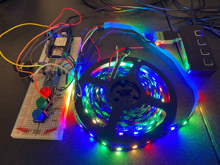
MotivationLED light strips are a popular way to liven up a dull dorm room. My room currently has some installed and are controlled by a small remote. However, I frequently lose my remote, hindering my ability to turn on my LEDs. Being able to turn on and off my LEDs from anywhere around my room by just clapping would remove the need for a remote and save time. Additionally, most LED strips I've seen are only able to uniformly display one color at a time. The LEDs in my LED strip are able to be individually coded, meaning they will be able to display multiple colors in different patterns at once. This design features a unique clap-on clap-off mechanism, as well as a warm colors, cool colors, and rainbow LED color pattern setting. These features will contribute to a unique user experience that I have not seen with LED lights that I have previously owned.
HardwareThe system block diagram and power block diagram for this device are shown below:
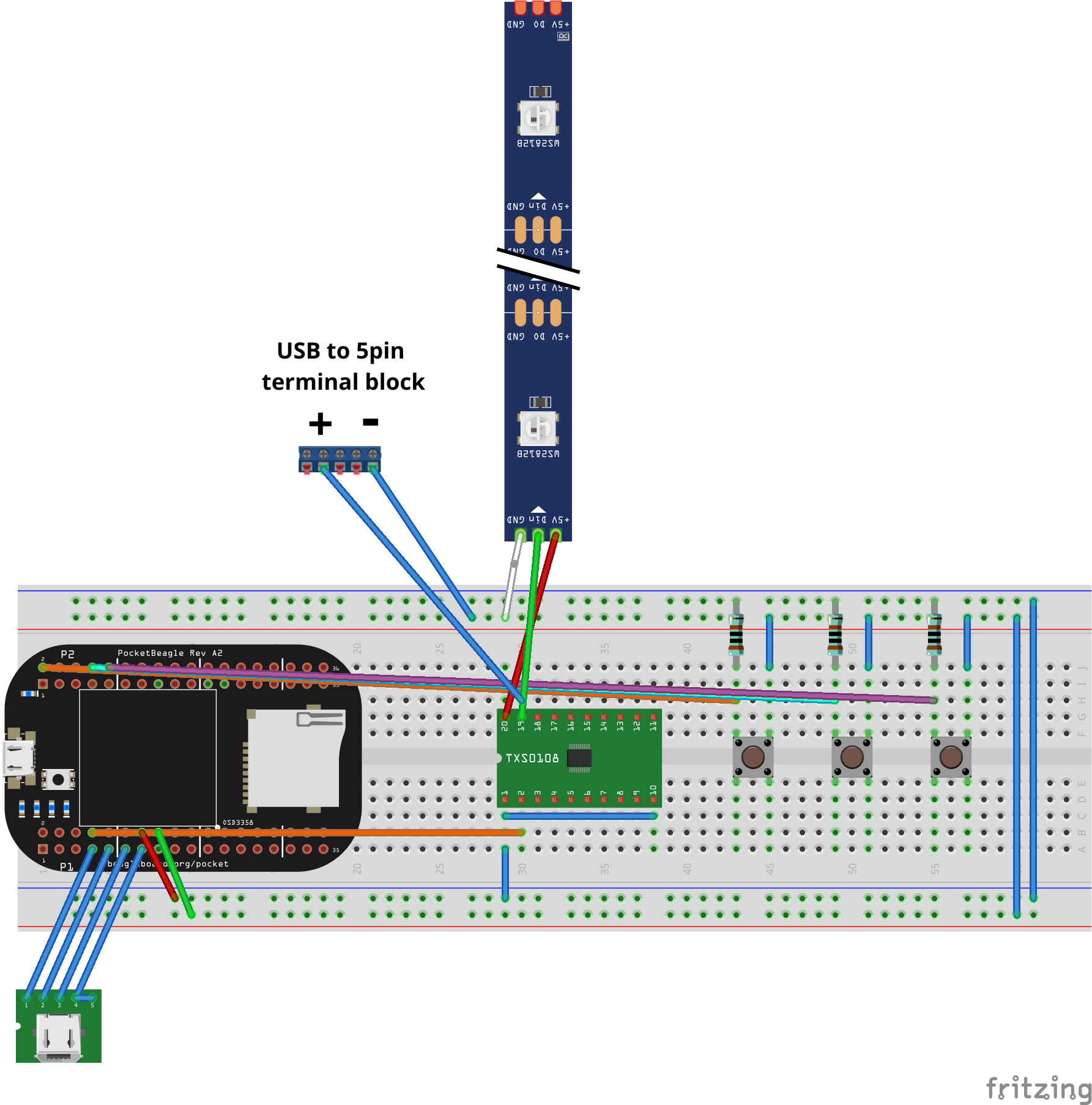
A Fritzing diagram of the overall circuit of this device is shown below:
Before inserting the Pocketbeagle on the breadboard, breadboard wires should be inserted ahead of time for the 5pin micro USB port. As shown in the photo, wires should be placed so that when P1_1 of the Pocketbeagle is inserted into hole 1a of the breadboard:
- P1_7 is connected to VCC of the USB port
- P1_9 is connected to D- of the USB port
- P1_11 is connected to D+ of the USB port
- P1_13 is connected to ID of the USB port
- ID and GND of the USB port should both be connected to each other
The micro USB to USB A adapter should then be inserted into the port followed by the USB A mini microphone. The Pocketbeagle can now also to inserted into the breadboard, where P1_1 would be inserted into hole 1a of the breadboard.
To provide power through the breadboard, the Pocketbeagle must be wired so that power can go through the power bus rails on either side of the breadboard. Using jumper wires:
- Connect P1_14 to the "+" power bus rail of the breadboard, this will provide 3.3 V through the rail
- Connect P1_16 to the "-" power bus rail of the breadboard, this will be the ground rail
- The rails on either side of the breadboard should also be connected together so that both sets of rails share the same power and ground.
The three push buttons will be used to switch between the three color pattern settings. They must be inserted in the middle of the breadboard so that the plastic nubs on the bottom fit into the groove at the center of the breadboard. A 1k Ohm resistor should be connected to the "+" power bus and one of the button terminals. A jumper wire should also be connected between the resistor and same button terminal to a GPIO pin on the Pocketbeagle. The other button terminal should be grounded by connecting it to the "-" rail of the breadboard using a jumper wire. Repeat the same steps for the other two buttons. I used P2_2, P2_4, and P2_6 for my GPIO pins.
To use connect the LED strip you must first connect the USB power hub to an outlet. The USB to 5pin terminal block can then be inserted into the USB hub. The level shifter will be inserted into the middle of the breadboard next to the push buttons. Connections are as follows:
- + port of the 5pin terminal block to VB pin
- - port of the 5pin terminal block to ground "-" rail
- VA pin to OE pin
- VA pin to 3.3 V "+" power rail
- A1 pin to P1_8 on Pocketbeagle
Using jumper cables the LED strip can also be connected to the level shifter.
- The 5V (red) wire of the LEDs will be connected to VB pin of the level shifter.
- The Data In (green) wire of the LEDs will be connected to the B1 pin of the level shifter.
- The ground (white) wire of the LEDs will be connected to the ground rail of the breadboard.
1. USB Mini Microphone Set-up
To set up the usb microphone, first run these sets of commands in Cloud9.
sudo apt-get update
sudo apt-get install -y swig libpulse-dev libasound2-dev
Once finished, run command
arecord -lOnce ran, make note of the device number and card number. Then run command:
nano ~/.asoundrcYou should see in the terminal pcm "hw:#, #" The first number should correspond to your card number, followed by your device number. If they do not match, edit the text accordingly. Once this is complete, your microphone should now be set up.
2. LED Strip Set-up
For the LED strip, first download and put the following files into a directory
- configure_pins.sh
- run
- run-opc-server
- opc-server
- opc.py
- config.json
- project.py
Note that configure_pins.sh, run, run-opc-server, opc-server must be given permissions 755. This can be done by running:
chmod 755 configure_pins.sh opc-server run run-opc-serverYou can check if this successfully worked by running command ls -l and checking to see if the files are highlighted green.
Also, the following PRU files must be in a subdirectory pru/bin/
- pru/bin/ws281x-original-ledscape-pru0.bin
- pru/bin/ws281x-original-ledscape-pru1.bin
We then must the following command to edit uENv.txt:
sudo nano /boot/uEnv.txtOnce the textbox appears, comment out the RPROC firmware and uncomment the UIO firmware.
Once that is complete run commands sudo reboot and ls /sys/class/uio to check that UIO is available.
Code Walkthrough
Brief overview of what the code is supposed to do:
This code should first connect the client to the server. It should then turn off all LED lights initially. Afterwards, it will then prompt the microphone to begin continuously collecting input data. Once a certain noise threshold from the environment is passed and power is on, the LED strip will turn on all white. If this threshold is passed while the LEDs are on, it will turn off all of the LEDs. When the LEDs are turned on, the user can press on the buttons to change the color settings of the LEDs. The three settings are warm colors, cool colors, and rainbow. The code is formatted so that unless the LEDs are first turned on by a clap, it will not turn on even when the buttons are pressed. Once it recognizes that a certain button is pressed while the lights are on, the color settings corresponding to that button are sent into the LEDs and are kept at that setting. The color setting functions are threaded so that the user can switch between settings at any time while the LEDs are on.
I will now go through some components of the code and the development process behind it.
I decided to use the Python module sounddevice to obtain sound level data from my microphone. My sounddevice code is largely based off of code I found on StackOverflow linked here. This code opens a stream, where sound data can be continuously gathered by the microphone. This stream is usually created by function sd.Stream, however, I ran into many issues with it recognizing the number of channels I needed for the stream. This issue was resolved by using the sd.InputStream function instead shown below. I had realized that the Stream function requires both an input and output. In my case, since I only require an input from the microphone, the InputStream function was used instead.
with sd.InputStream(channels = 1, callback=print_sound):Once the stream has started, the sound data is then displayed as lines in the terminal, so that we are able to easily visually see the sound level that is going through the microphone. The more lines there are in the terminal, the louder the input sound is. I used this information to create a sound level threshold so that my LED lights would run after this sound threshold was passed through clapping.
if volume_norm > 20:
        if power:
            STR_LEN=240
            for i in range(STR_LEN):
                leds = [(0, 0, 0)] * STR_LEN

            if not client.put_pixels(leds, channel=0):
                print ('not connected')
            power = False
            sd.sleep(300)
        else:
        # Define Pixel String
            STR_LEN=240
            for i in range(STR_LEN):
                leds = [(255, 255, 255)] * STR_LEN

            if not client.put_pixels(leds, channel=0):
                print ('not connected')
            power = True
            sd.sleep(300)
I also have a class called ledsetting. This class contains all of my buttons and initializes them. Inside this class, there are three defs corresponding to each of the three buttons. def warm is used to change the LEDs to the warm color setting, def cold is used to change the LEDs to the cool color setting, and def rainbow is used to change the LEDs to the rainbow setting. Each def is set up so that once the button is pressed, the color array is sent to the LEDs to change their color. The for loop changes their colors in a sets of three for the entire length of 240 LEDs. The same code format was used for the cool colors and rainbow setting, except with the rainbow I needed to change a set of 6 LEDs at a time.
def warm(self):
        while(1):
            while(GPIO.input(self.warm_button) == 1): #waiting for press
                time.sleep(0.1)
            if power:
                for i in range(0,STR_LEN,3): #change color array
                    leds[i] = (255, 0, 0)
                    leds[i+1] = (255, 64, 0)
                    leds[i+2] = (255, 128, 0)
                if not client.put_pixels(leds, channel=0): #sends color array over
                    print ('not connected')
            # Wait for button release
            while(GPIO.input(self.warm_button) == 0):
                # Sleep for a short period of time to reduce CPU load
                time.sleep(0.1)
    # End def
When I first created the buttons, I had to program them so that the buttons were able to be switched between at anytime while the LEDs were on. This means that I needed all three color setting defs to be continuously running at the same time. This led to me using threads. By creating a thread of buttons, I was able to have all three color settings able to freely be alternated between.
with sd.InputStream(channels = 1, callback=print_sound):
        import threading

        color_settings = ledsetting()
        # threading allows for buttons to be switched between
        try:
            thread1 = threading.Thread(target=color_settings.warm)
            thread2 = threading.Thread(target=color_settings.cold)
            thread3 = threading.Thread(target=color_settings.rainbow)
            thread1.start()
            thread2.start()
            thread3.start()
            thread1.join()
            thread2.join()
            thread3.join()
Something I was not able to get to work was the auto-start on boot. I tried using "cron" to have my program start running right when the Pocketbeagle was booted. This was attempted by using command:
sudo crontab -eOnce the textbox came up, I then entered the following commands into the terminal:
@reboot sleep 15 && sh /var/lib/cloud9/ENGI301/python/project/run-opc-server > /var/lib/cloud9/ENGI301/python/project/cronlog 2>&1
@reboot sleep 15 && sh /var/lib/cloud9/ENGI301/python/project/run >> /var/lib/cloud9/ENGI301/python/project/cronlog 2>&1
However, this was not successful. I had errors in the cronlog from the sounddevice module not being able to properly recognize my device. More troubleshooting is required to get the auto-start component to work properly.
OperationFirst plug the USB hub into an outlet. Make sure you press the button on the USB hub to send power to your LED light strip. A micro USB to USB A cable should be used to connect the Pocketbeagle to your laptop.
Two terminals must be used to run the code. The command
sudo ./run-opc-servershould be entered into the first terminal to run the server. Then, the command
./runshould be entered into the second terminal to run the main code. Once the commands are initialized, all of the LEDs in the strip should be completely off. Clap your hands to turn on the LEDs. They should all be turned on colored white. Once the LED lights are on, you can change the color settings by pressing the buttons on the breadboard. Pressing the push button connected to P2_2 will set the LEDs to the warm colors mode. Pressing the push button connected to P2_4 will set the LEDs to the cool colors mode. Pressing the push button connected to P2_6 will set the LEDs to the rainbow colors mode. You can clap again while the LEDs are on to turn the LED strip off.
Conclusion and Future StepsOverall, making this project was a challenging yet rewarding experience. I greatly underestimated the complexity of the software component of this project and there was a steep learning curve that I had to get over. However, once I started able to get components of the device working, it was very satisfying and made the effort worth it. The trickiest part of making this device was probably the sound level component, because a lot of the Python modules like pyaudio and wave did not recognize my microphone for some reason, hindering my ability to use them. I'd like to give special thanks to my professor Erik Welsh, for giving so much time into helping me out with this project. Without his help, I could not have completed this project.
Some future steps for this device include:
- Integrating a light sensor to change the brightness of the LEDs depending on the ambient lighting of the room. This feature was included in my original proposal, but was excluded due to time constraints
- Making the microphone able to differentiate between claps and other noises that surpass the noise level threshold.
- Adding more color pattern settings
- Adding motion into the led light settings. For example having a flashing strobe light setting, or a setting where a section of LEDs turn on and off down the strip, making it look like the light is moving back and forth on the strip.


Comments
Please log in or sign up to comment.