

Hardware components | ||||||
 |
| × | 1 | |||
| × | 1 | ||||
| × | 1 | ||||
Software apps and online services | ||||||
| ||||||
| ||||||
| ||||||
Infra-red image processing started to take over the automotive industry, because it is not sensitive to visible light. Application like tracking human behavior in the car is monitored to prevent accidents, these can be falling asleep while driving keeping track if the driver is paying attention to the road and so on.
IR cameras can see the human eye even through sunglasses, and the cameras image is not affected from daylight or if its night, and there is from very little to none ambient light. The cameras have their own light source, LED's mounted next to the lens.
This project shows some image processing algorithms that improve the quality of the image for it to be further processed. Algorithms like face detection and/or Eyegaze are very common application. But for them to work properly good quality image is remanded at the algorithm input.
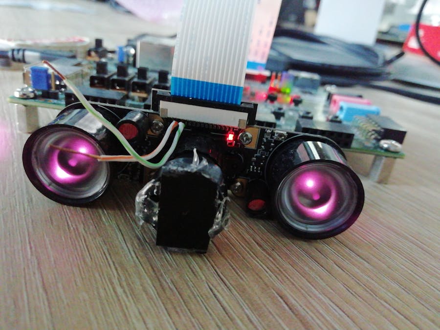
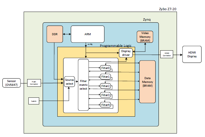
The selected device is a Zybo Z7-20 SoC, the camera a cheap Raspberry PI camera with two IR LED's with a maximum resolution of 1080p@60Hz.
The architecture presented in this project is extendable, more algorithm can be added with ease.
The TheoryI selected five image processing algorithms all based on 3x3 kernels:
· Stuck/dead pixel correction
This is a general issue for all type of sensors, it is a common preprocessing algorithm.
· Median filter
Common noise smoothing preprocessing algorithm.
· Low-pass filter (Smoothing filter)
Noise smoothing, the distribution of this kernel smooths the image, and will not blur the image as much as the median filter.
· Image Sharpening
Improves the quality of the image by "edge crispening", that is accentuate the edges.
· Edge detection
There must be a border applied to the image after applying one of these algorithms the image size is reduced.
All the algorithms are based on 3x3 kernels that is why all of the processing elements(PE), have to communicate with a FIFO, each PE has a latency of one line. The kernel can be applied only when the second line of data arrives, considering that a border is applied to the image to get the same image dimension at the output.
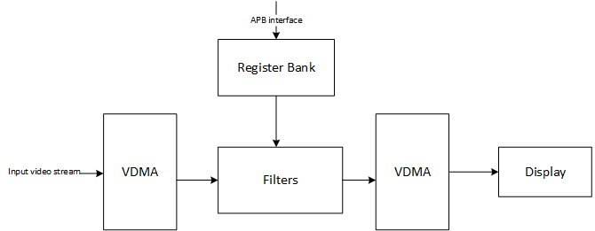
The selector module is an extendable MUX network, In this case with five image processing algorithms it consists of the six MUX-es in cascade, one for each filter output and one for the input signal. The data flow can be configured in this case the video stream gets from the input to the output, the order and number of the image processing elements it passes is configurable.
The structure of a processing element is shown below, basically in this case is a delay line with that has the video stream as input and outputs a 3x3 matrix. The module next to it will apply the kernel and the output is the processed frame.
The project extends the PCam 5C Demo (https://reference.digilentinc.com/learn/programmable-logic/tutorials/zybo-z7-pcam-5c-demo/start). In that architecture I inserted my module between the VDMA and the GammaCorrection module.
Another difference is that I added a FIFO for each line buffer.
InterfacingAll the modules use the so called Frame Interface(FI) that is very similar to the AXI Stream interface used in the reference design, a conversion can be made between the two. From AXI Stream to Frame there is no need for conversion, the other way around some additional signals must be generated. The AXI Stream interface only has start of frame and end of line control signals.
module axi_stream2frame#(
 parameter DATA_WIDTH = 24
)(
 input                       clk                   , // Syste clock
 input                       rst_n                 , // Asynchronous reset active low
//------------------------- Configuration interface ----------------------------------
 input  [11:0]               cfg_img_w             , // Image width
 input  [11:0]               cfg_img_h             , // Image width
//------------------------- AXI-Stream interface -------------------------------------
 input                       m_axi_stream_tuser    , // Start of frame
 input                       m_axi_stream_tvalid   , // Slave has valid data
 input                       m_axi_stream_tlast    , // End of frame
 input     [DATA_WIDTH-1:0]  m_axi_stream_tdata    , // Data transferred
 output                      m_axi_stream_tready   , // Master is ready to receive
// ------------------------------ Frame Interface -----------------------------------
 output reg                  s_frm_val             , // Master has valid data
 input                       s_frm_rdy             , // Slave is ready to receive
 output reg [DATA_WIDTH-1:0] s_frm_data            , // Data transferred
 output reg                  s_frm_sof             , // Start of Frame
 output reg                  s_frm_eof             , // End of Frame
 output reg                  s_frm_sol             , // Start of Line
 output reg                  s_frm_eol               // End of Line
);
reg [11:0] pix_cnt ;
reg [11:0] line_cnt;
wire invalrdy;
wire outvalrdy;
wire set_eof;
assign invalrdy = m_axi_stream_tvalid & m_axi_stream_tready;
assign outvalrdy = s_frm_rdy & s_frm_val;
assign m_axi_stream_tready = s_frm_rdy;
assign set_eof = (line_cnt == (cfg_img_h - 1'd1)) & m_axi_stream_tlast & invalrdy;

always@(posedge clk or negedge rst_n)
if(~rst_n                        ) pix_cnt <= 11'd0         ; else
if(m_axi_stream_tuser & invalrdy ) pix_cnt <= 11'd0         ; else // Reset at start of frame
if(m_axi_stream_tlast & invalrdy ) pix_cnt <= 11'd0         ; else // Reset at end of frame
if(invalrdy                      ) pix_cnt <= pix_cnt + 1'd1;      // Increment at each pixel
always@(posedge clk or negedge rst_n)
if(~rst_n                       ) line_cnt <= 11'd0          ; else
if(m_axi_stream_tuser & invalrdy) line_cnt <= 11'd0          ; else // Reset at start of frame
if(m_axi_stream_tlast & invalrdy) line_cnt <= line_cnt + 1'd1;      // Increment at each pixel
always@(posedge clk or negedge rst_n)
if(~rst_n                              ) s_frm_sol <= 1'b0; else
if(outvalrdy & s_frm_sol               ) s_frm_sol <= 1'b0; else // Reset sol is transmitted
if(m_axi_stream_tuser & invalrdy       ) s_frm_sol <= 1'b1; else // Set start of line after last pixel of line is transmitted
if(outvalrdy & s_frm_eol & (~s_frm_eof)) s_frm_sol <= 1'b1;      // Set at start of frame
always@(posedge clk or negedge rst_n)
if(~rst_n               ) s_frm_eof <= 1'b0; else
if(outvalrdy & s_frm_eof) s_frm_eof <= 1'b0; else // Reset after eof is transmitted
if(set_eof              ) s_frm_eof <= 1'b1;      // Set when last pixel is received
always@(posedge clk or negedge rst_n)
if(~rst_n                            ) s_frm_val <= 1'b0; else
if(s_frm_rdy & (~m_axi_stream_tvalid)) s_frm_val <= 1'b0; else // Reset when ready and no valid data at the input
if(invalrdy                          ) s_frm_val <= 1'b1;   // Set if data is received
always@(posedge clk or negedge rst_n)
if(~rst_n                       ) s_frm_eol <= 1'b0; else
if(outvalrdy & s_frm_eol        ) s_frm_eol <= 1'b0; else // Reset after eol is transmitted
if(m_axi_stream_tlast & invalrdy) s_frm_eol <= 1'b1;      // Set when last pixel in a row is received
always@(posedge clk or negedge rst_n)
if(~rst_n                        ) s_frm_sof <= 1'b0; else
if(outvalrdy & s_frm_sof         ) s_frm_sof <= 1'b0; else // Reset after sof is                               transmitted
if(m_axi_stream_tuser  & invalrdy) s_frm_sof <= 1'b1;      // Set when first pixel is received
always@(posedge clk or negedge rst_n)
if(~rst_n  ) s_frm_data <= {(DATA_WIDTH){1'b0}}; else
if(invalrdy) s_frm_data <= m_axi_stream_tdata  ;
endmodule //axi_stream2FrameThis camera is used with Raspberry Pi, all drivers are closed source, so there was no configuration example. I soldered two wires on the I2C pins on the SCL an SDA pins. Connecting the camera to a Raspeberry Pi and a logic analyzer to the soldered wires, i followed the camera interfacing guide https://projects.raspberrypi.org/en/projects/getting-started-with-picamera
The logic analyzer decoded the I2C, the excel of the dumped values will be attached at the end.
The configuration was added in the C++ code.
The camera is an RGB one, and is only IR when there is dark in the room. To resolve this I glued piece of plastic from the front of a remote control, the filter that is in front of the IR LED that sends the command to the TV. Not a pretty solution but is works.
For configuration APB interface is used.
void filter_cfg()
{
	Xil_Out32(APB_BASE_ADDR + CFG_IMG_WIDTH_ADDR, IMG_W);
	Xil_Out32(APB_BASE_ADDR + CFG_IMG_HEIGHT_ADDR, IMG_H);
	Xil_Out32(APB_BASE_ADDR + CFG_PIX_CORR_SEL_ADDR, 0);
	Xil_Out32(APB_BASE_ADDR + CFG_SHARP_SEL_ADDR, 0);
	Xil_Out32(APB_BASE_ADDR + CFG_SMOOTH_SEL_ADDR, 0);
	Xil_Out32(APB_BASE_ADDR + CFG_MEDIAN_SEL_ADDR, 0);
	Xil_Out32(APB_BASE_ADDR + CFG_LAPLACE_SEL_ADDR, 0);
	Xil_Out32(APB_BASE_ADDR + CFG_OUTPUT_SEL_ADDR, 0);
	Xil_Out32(APB_BASE_ADDR + CFG_PIX_CORR_THR_ADDR, 0);
	Xil_Out32(APB_BASE_ADDR + CFG_SHARP_COEF_ADDR, 0);
	Xil_Out32(APB_BASE_ADDR + CFG_TEST_MODE_EN_ADDR, 0);
}
The configuration presented above is the the selection of the each selector module. Now it is configured so that the input stream will go to the output without any processing.
void filter_cfg()
{
	Xil_Out32(APB_BASE_ADDR + CFG_IMG_WIDTH_ADDR, IMG_W);
	Xil_Out32(APB_BASE_ADDR + CFG_IMG_HEIGHT_ADDR, IMG_H);
	Xil_Out32(APB_BASE_ADDR + CFG_PIX_CORR_SEL_ADDR, 0);
	Xil_Out32(APB_BASE_ADDR + CFG_SHARP_SEL_ADDR, 0);
	Xil_Out32(APB_BASE_ADDR + CFG_SMOOTH_SEL_ADDR, SMOOTH_IN_CODE);
	Xil_Out32(APB_BASE_ADDR + CFG_MEDIAN_SEL_ADDR, 0);
	Xil_Out32(APB_BASE_ADDR + CFG_LAPLACE_SEL_ADDR, SMOOTH_IN_CODE);
	Xil_Out32(APB_BASE_ADDR + CFG_OUTPUT_SEL_ADDR, LAPLACE_IN_CODE);
	Xil_Out32(APB_BASE_ADDR + CFG_PIX_CORR_THR_ADDR, 0);
	Xil_Out32(APB_BASE_ADDR + CFG_SHARP_COEF_ADDR, 0);
	Xil_Out32(APB_BASE_ADDR + CFG_TEST_MODE_EN_ADDR, 0);
}
Xil_Out32(APB_BASE_ADDR + CFG_SMOOTH_SEL_ADDR, SMOOTH_IN_CODE);
Putting the its own input to a processing element will be treated for it to gain the global input, to avoid eventual configuration errors, normally it would connect the input to the output and the module will not work.
The DemoI showcased a laplacian filter with and without smoothing, we can observe the image is noisy and after applying the smoothing filter only the edges remain.
To compare the two images original and processed I added a second VDMA before my module, after the Gamma correction, now both corrected and original image is in the DDR, so I can copy crop the processed image and replace the cropped area with the original.
I reused an older project a AXI read driver, so I can load an image to the DDR and be able to read it to test the system without a camera.
To use the git project follow this guide https://reference.digilentinc.com/learn/programmable-logic/tutorials/github-demos/start
AttachmentsI2C decoded csv https://github.com/hszilard13/Infa-red-based-Image-processing-Zybo/blob/master/config_1080p_rgb.csv


Comments