


Hardware components | ||||||
 |
| × | 1 | |||
 |
| × | 1 | |||
| × | 1 | ||||
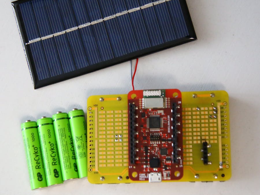
HARDWARIO kit is already very battery friendly. But in some cases and combination of sensors or turned on radio your power consumption will go higher. Here I explain simple hack of Battery Module how to add recharging.
NiMH BatteriesYou can use NiMH batteries alone in Battery Module perfectly fine. The smaller issue is that the cell has 1.2V instead of alkaline 1.5V. This way you loose some capacity. So instead of 18 months battery life you could get "just" 12 months. But you save money by recharging batteries instead of throwing them away.
Let's try to chage the batteries directly in the Battery Module and get basically infinite life "on batteries"
Battery Module DC/DC controllerIn Battery Module schematics you can see that the board is using TPS62745 DC/DC step-down converter
This controller is using up to 6.4V from four AAA batteries to create 3V for the MCU and all other modules. In datasheet there is an information that this chip should work for votlages up to 10V.
This makes possible to connect smaller 6V solar panel to recharge batteries.
Solar PanelJust google 6V solar panel and you find lot of them. The ideal panel will have 6V, output power around 1W and 200mA. This current is also perfect for self-regulating of the charge current of the NiMH batteries.
You need just a one last thing in the circuit - diode.
DiodeDiode allows the current to flow only from solar panel to the batteries. Otherwise at night the batteries could discharge a bit thanks to solar panel internal resistance.
Luckily we've added this diode to the newest R1.4. Please make sure or ask before ordering at HARDWARIO that you will get this newest R1.4 if you would like to have diode already soldered in. In the schematics below connect Solar panel minus to pin 3 (labeled SOL-) and plus to pin 2 (labeled SOL+).
If you have older R1.3, you have to solder diode yourself. The diode is connected in the series with solar panel. It is better to have normal (not shottky) diode because the 0.7V voltage drop.
Schematics
No need for schematics :) See pictures below. Just solder the solar panel to the + and - pins on the Battery Module and put the diode in series. The diode needs to be oriented that the "band" is close to the + pin on the Battery Module.
You can also see how you batteries are charging because Core Module is measuring battery voltage and it is sending the voltage over radio.


Comments
Please log in or sign up to comment.