Customizing light arrangement using IoT.
This IoT light is for a big classroom where the switch is wired to turn on/off the entire row/column of lights, which is very inefficient and inconvenient. This creation uses relays to control every single light via smartphone.
Big rooms have many rows and columns of lights. Customizable light switch enables the user to turn on the lights however he wants via smartphone. Now people don’t have to switch on and off all the way to find the light arrangement that suits. I used Blynk app to make buttons for each option. He also connected typical light bulb with Genuino 101, using relay module.
In classroom, pre-set lights arrangement was very inconvenient because it turned on/off the entire column of lights which made it impossible to turn on the lights only at the back of the class for the students who reads instead of watching movies.
I thought it would be lot more convenient if every single light had a relay and lights could be arranged to whatever way needed. So I connected relays to the lights and programmed to control them via smartphone.
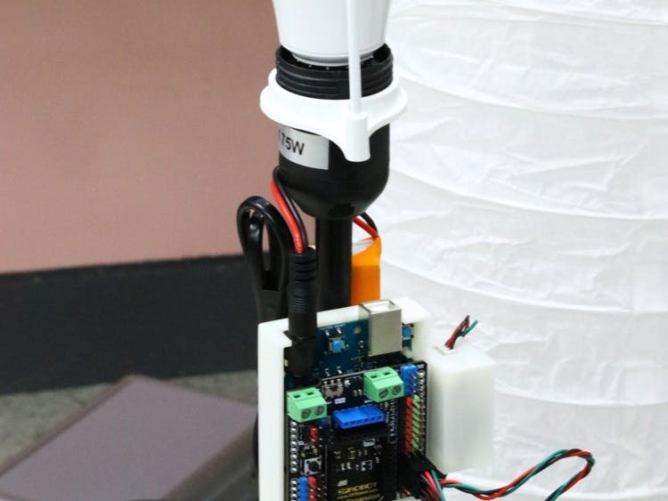
This is the platform I used for the project: Genuino 101 board.
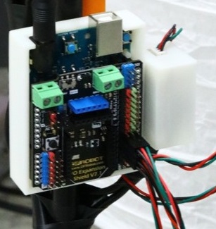
It is a I/O shield for 101’s expansion, produced by DFRobot.
This is a relay module I used to control the flow of 220v electricity. It works as a switch in the project. Also produced by DFRobot.
However, 220v can be very dangerous and could lead to deadly electric shock. So I 3D printed a case for the relays.
The first trial was not successful as the printed result was too tight for the relays even though the measurements were correct - probably because ABS materials contracted after the printing. I tried again with PLA materials and the relays perfectly fit to the cases.
To connect light bulbs’ wire with relays, I stripped the switch part of the wire.
Cut it to fit the size of relay module and tape them with insulation tapes.
Connect insulated wires to relay module’s COM port and NO port.
Connect them with Genuino 101 board and test if it works.
I used 4 lights bulbs for the project so you have to go through 3 more.
Now we will write code for the 101 board. Use Blynk connection example to connect it with BLE.
#define BLYNK_PRINT Serial
#include <BlynkSimpleCurieBLE.h>
#include <CurieBLE.h>
char auth[] = "YourAuthToken";
BLEPeripheral  blePeripheral;
BLYNK_WRITE(V1)
{
 int value = param.asInt();
 if(value==1){
 digitalWrite(2, HIGH);
 digitalWrite(3, HIGH);
 digitalWrite(4, HIGH);
 digitalWrite(5, HIGH);
 } else{
 digitalWrite(2, LOW);
 digitalWrite(3, LOW);
 digitalWrite(4, LOW);
 digitalWrite(5, LOW);
 }
}
BLYNK_WRITE(V0)
{
 int value = param.asInt();
 if(value==1){
 digitalWrite(2, HIGH);
 digitalWrite(3, HIGH);
 } else{
 digitalWrite(2, LOW);
 digitalWrite(3, LOW);
 }
 }
 BLYNK_WRITE(V2)
{
 int value = param.asInt();
 if(value==1){
 digitalWrite(4, HIGH);
 digitalWrite(5, HIGH);
 } else{
 digitalWrite(4, LOW);
 digitalWrite(5, LOW);
 }
 }
 BLYNK_WRITE(V3)
{
 int value = param.asInt();
 if(value==1){
 digitalWrite(2, HIGH);
 digitalWrite(4, HIGH);
 } else{
 digitalWrite(2, LOW);
 digitalWrite(4, LOW);
 }
 }
 BLYNK_WRITE(V4)
{
 int value = param.asInt();
 if(value==1){
 digitalWrite(3, HIGH);
 digitalWrite(5, HIGH);
 } else{
 digitalWrite(3, LOW);
 digitalWrite(5, LOW);
 }
 }
 BLYNK_WRITE(V5)
{
 int value = param.asInt();
 if(value==1){
 digitalWrite(2, HIGH);
 digitalWrite(5, HIGH);
 } else{
 digitalWrite(2, LOW);
 digitalWrite(5, LOW);
 }
 }
 BLYNK_WRITE(V6)
{
 int value = param.asInt();
 if(value==1){
 digitalWrite(3, HIGH);
 digitalWrite(4, HIGH);
 } else{
 digitalWrite(3, LOW);
 digitalWrite(4, LOW);
 }
 }
 BLYNK_WRITE(V7)
{
 int value = param.asInt();
 if(value==1){
 digitalWrite(2, HIGH);
 delay(750);
 digitalWrite(3, HIGH);
 digitalWrite(2, LOW);
 delay(750);
 digitalWrite(5, HIGH);
 digitalWrite(3, LOW);
 delay(750);
 digitalWrite(4, HIGH);
 digitalWrite(5, LOW);
 delay(750);
 digitalWrite(4, LOW);
 }
}
void setup() {
 Serial.begin(9600);
 delay(1000);
 pinMode(2, OUTPUT);
 pinMode(3, OUTPUT);
 pinMode(4, OUTPUT);
 pinMode(5, OUTPUT);
 blePeripheral.setLocalName("101");
 blePeripheral.setDeviceName("101");
 blePeripheral.setAppearance(384);
 Blynk.begin(blePeripheral, auth);
 blePeripheral.begin();
 Serial.println("Waiting for connections...");
}
void loop() {
 Blynk.run();
 blePeripheral.poll();
 }
Upload the code and now we’ll work on Blynk app.
Dx buttons are for each light and Vx buttons are frequently used customized arrangements set in the source code.
V1 = All lights on.
V0 = turn on D2, D3
V2 = turn on D4, D5
V3 = turn on D2, D4
V4 = turn on D3, D5
V5 = turn on D2, D5
V6 = turn on D3, D6
V7 = turn on D2-D3-D5-D4 in combo.
This is the final step. You have to connect relays to 101 board.
See the code and connect the relays to their corresponding ports.
Now the project is finished. You can cover the lights with some fabrics for better mood.


_baVEVgguW1.jpg?auto=compress%2Cformat&w=48&h=48&fit=fill&bg=ffffff)


Comments