


Hardware components | ||||||
| × | 2 | ||||
 |
| × | 1 | |||
 |
| × | 1 | |||
 |
| × | 1 | |||
 |
| × | 2 | |||
 |
| × | 2 | |||
Software apps and online services | ||||||
 |
| |||||
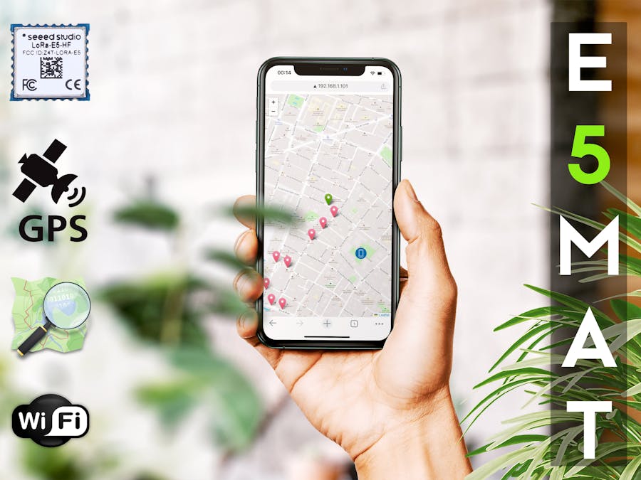
This tutorial is about the implementation of LoRa GPS tracker based on Wio-E5 Wireless Module. Coordinates will be sent from the Transmitter to the Receiver by LoRa Technology, after processing on the Receiver, the Transmitter's location on the map can be seen live. There is no need to install the app to display the map on the phone.
Grove Wio-E5 embedded with Wio-E5 STM32WLE5JC, powered by ARM Cortex M4 ultra-low-power MCU core and Long Range SX126x, is an easy-to-use wireless radio module, as the world-first combo of Long Range RF and MCU chip into one single tiny module, it supports (G)FSK, BPSK, (G)MSK, and Long Range modulations, and is FCC, CE certified. Grove - Wio-E5 features extremely compacted size, ultra-low power consumption, low cost, and amazing performance.
- Wio-E5 (STM32WLE5JC) embedded
- Support LoRaWAN protocol on EU868/US915 frequency band
- Ultra-long transmitting range up to 10km (Ideal value in open space)
- Easy control by AT command via UART connection
- Rapid prototyping with plug-and-play Grove interfaces
- Ultra-low power consumption and high performance
By connecting Grove - Wio-E5 to your development boards, your devices are able to communicate with and control Wio-E5 conveniently by AT command through UART connection. Grove LoRa-E5 will be a superior choice for IoT device development, testing, and long-distance, ultra-low power consumption IoT scenarios like smart agriculture, smart office, and smart industry. It is designed with industrial standards with a wide working temperature at -40℃ ~ 85℃, high sensitivity between -116.5 dBm and -136 dBm, and power output between 10 dBm and 22 dBm.
Free Wio-WM1110 Project Sponsorship with Seeed Fusion PCBA:
If you have an interesting concept for Wio-WM1110 and are willing to share it with the community, share it with us and we can help you make it a reality with Seeed Fusion’s one-stop-shop capabilities. Each person is limited to two PCBA boards 100% completely FREE for one design, including PCB fabrication, the cost of parts, assembly and shipping. The design must include Wio-WM1110. Click here for more information!
What is LoRa?LoRa is a Long-Range radio technology developed by Semtech. Here is a definition from Semtech's LoRa FAQ:
LoRa (Long Range) is a modulation technique that provides significantly longer range than competing technologies. The modulation is based on spread-spectrum techniques and a variation of chirp spread spectrum (CSS) with integrated forward error correction (FEC). LoRa significantly improves the receiver sensitivity and as with other spread‐spectrum modulation techniques, uses the entire channel bandwidth to broadcast a signal, making it robust to channel noise and insensitive to frequency offsets caused from the use of low cost crystals. LoRa can demodulate signals 19.5dB below the noise floor while most frequency shift keying systems (FSK) need a signal power of 8-10dB above the noise floor to demodulate properly. The LoRa modulation is the physical layer (PHY), which can be utilized with different protocols and in different network architecture – Mesh, Star, point to point, etcetera.
You can read this article for more information.
Features of this project- Live tracking on OpenStreetMap or Mapbox (It can be used on other Map services with minor changes)
- No need to install the app on the mobile phone
- Easy to use and Plug-an-play, without need soldering
- Ultra long transmitting range up to 10km (Ideal value in open space and using an external antenna)
- Automatic saving of data on Google Sheets
- Display the location of the Transmitter and Receiver simultaneously on the map
- Calculate the distance between Transmitter and Receiver. (in kilometers, miles, meter)
- Suitable for the Hikers, Nature explorers, Elderly, Children, Pets and etc.
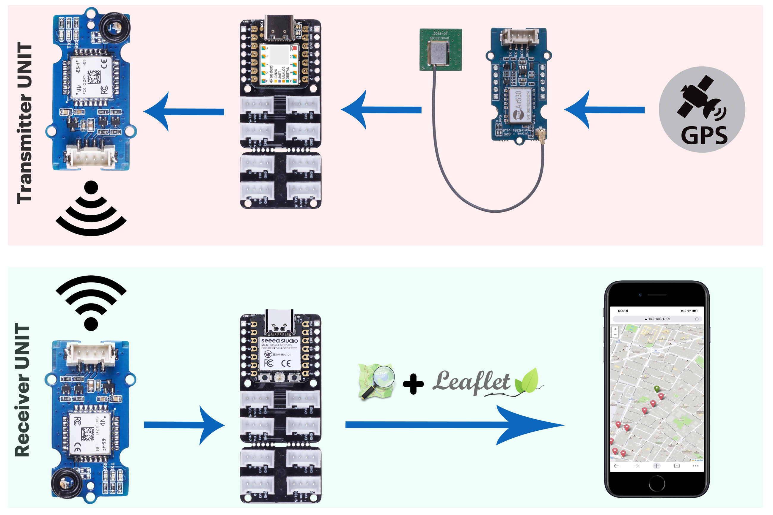
This project is the implementation of a P2P communication. The figure below shows how the transmitter and receiver units work.
I have already done a similar project using Grove Long Range Radio module (old version of Grove LoRa Module) which can be seen here, but in this project I used a pair of Grove Wio-E5 module's. GPS coordinates are received from the GPS module (Grove GPS Air530) and sent to the Receiver by Grove Wio-E5 module and LoRaE5 library.
void loop(void)
{
    unsigned long currentMillis = millis();
    while (GPSserial.available() > 0){
  		if (gps.encode(GPSserial.read())){
  		  if (currentMillis - previousMillis >= interval) {
    			previousMillis = currentMillis;
    			if (gps.location.isValid()){
    			  String GPSData = (String(gps.location.lat(), 6)) + "," + (String(gps.location.lng(), 6));
    			  lora.transferPacketP2PMode((char *)GPSData.c_str());
    			  SerialUSB.println("[GPS data has been sent.]");
    			}
  		  }
  	   }
  }
}
The sent LoRa packet only contains Transmitter coordinates which is as follows and includes latitude and longitude:
52.230195,21.013293The interval between each packet sending is completely optional, which I considered 10 seconds. This time can be changed by the user in Transmitter source code.
const long interval = 10000;On the receiver side, the information is received by Grove Wio-E5 module and processing begins. GPS coordinates are extracted and for use by the web server, it is placed in the incomingString and gpsDATA variables.
The web server connects to the hotspot created by the phone or your router. After opening the IP of the web server by the web browser of the phone (Chrome web browser is recommended), Transmitter location is displayed to the user with the help of leafletjs and OSM map.
One of the important features of this project is that the user does not need to install any application on the mobile phone and only uses the phone's web browser and internet connection through the mobile data is required.
Each time a marker is displayed on the map, its location is sent to Google sheets for future use. For this I used this tutorial.
⚠️ Be careful, you have to replace the link of your Google sheets in the index.h file.
The Arduino IDE has been used for this project and the following libraries have been installed.
- TinyGPSPlus [v1.0.3a]
- LoRaE5 [v0.1.1]
It is necessary to add the required files for compilation through Boards Manager in Arduino. See here and here to get started. The complete source code of the project can be downloaded from here.
E5MAT works with two units:
Part 1: Transmitter unitIn this section, Grove modules are connected to the Seeeduino XIAO SAMD21 as shown below. XIAO SAMD21 is the best choice at this stage due to its small size and high capabilities. I used Grove Shield for Seeeduino XIAO to connect the Grove modules to XIAO. For convenience, I put a pre-made XIAO firmware in my Github page.
To protect the modules, I used a ready-made enclosure. A high capacity lithium battery is recommended. We connect the battery directly to Grove Shield for Seeeduino XIAO.
These boxes can be bought from Chinese stores like AliExpress. Also, a Rocker Switch to turn the device on and off was placed on the box, which can be directly connected between the battery and XIAO Grove Shield.
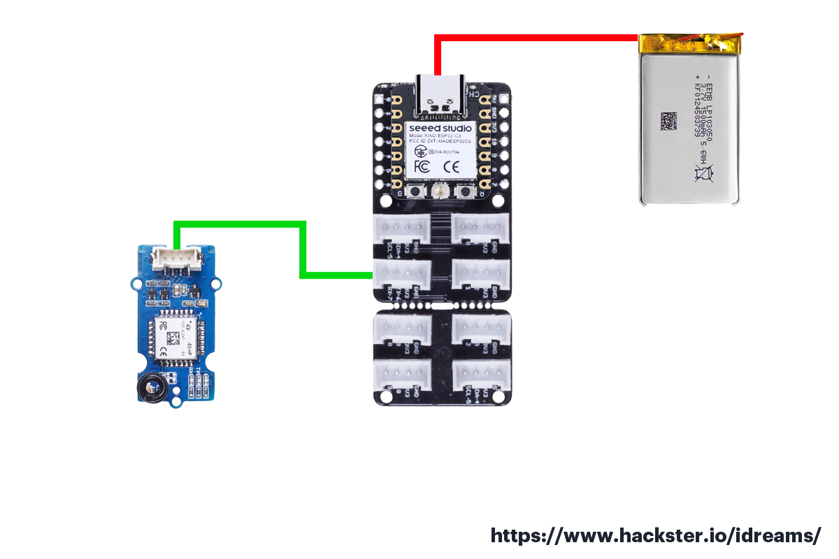
Part 2: Receiver unitFor the receiving side, the best option is XIAO ESP32C3. Seeed Studio XIAO ESP32C3 adopts new RISC-V architecture, supporting both Wi-Fi and BLE wireless connectivities. For Internet of Things applications, you will find it is flexible and suitable for all kinds of IoT scenarios.
Just connect the Grove Wio-E5 to it. For this we use Grove Shield for XIAO or XIAO Expansion Board. Here we use lithium battery for power supply.
Of course, the following boards can also be used here because they have a Grove port:
- AtomU ESP32 Development Kit
- M5Stack Timer Camera
- M5StickC ESP32
- TTGO T-OI PLUS RISC-V ESP32-C3
- TTGO T-Dongle ESP32-S2 Development Board
We use a case/box for protection and portability.
To receive a map on a mobile phone or PC, it is necessary to save Wi-Fi settings in the Receiver.ino file. If you use a mobile phone, make sure that the mobile data and location sensor are turned on. To setup and connect the receiver to the mobile phone, you need to create a hotspot on the phone or if you are using a PC, give your home router username and password. Pay attention that the Wi-Fi name and its password must be the same as the Wi-Fi connection settings in the Arduino codes. After connecting the receiver to the mobile phone, you can see the IP address of the receiver by referring to the hotspot settings.
⚠️ Remember this IP to call the web server in the web browser.
After running the web server in the phone browser, the location of the Transmitter can be seen live on the map. The green marker shows the current location of the Transmitter and the red markers show the previous locations of the Transmitter. The blue icon is the location of the mobile phone (or yourself), whose coordinates are taken from the phone's GPS.
Because the request to use the phone location service must be sent from an HTTPS server, it is necessary to enter the Transmitter IP address in the Chrome browser settings (The server built by XIAO ESP32C3 is an HTTP server). For this, open Chrome mobile web browser and type the following address:
chrome://flags/#unsafely-treat-insecure-origin-as-secureEnter Transmitter IP in the box and change Disabled to Enabled. Now you can see your location on the map. Pay attention that the location sensor must be on.
⚠️ It seems that this feature is not available in Chrome browser for iOS.
In this part, we developed an Android app by MIT app inventor. We want to read the data sent on the USB serial port by connecting the Receiver to the mobile phone (via OTG adapter) and display the Transmitter location on the map.
As you can see, the mobile phone and Transmitter location can be seen on the map (RED Marker). In this case, no power supply is required. By changing the Google sheets link (this link was created in the previous steps) in the code, the information can be sent to Google Sheets.
After connecting the board to the phone through the OTG adapter, press the open button. The source code of this section can be downloaded from here.
Important points1. You should not be in a closed place to receive the GPS signal on the mobile phone and the Transmitter side.
2. Be aware that the GPS connection time may take up to a few minutes.
3. By connecting the temperature sensor or any other sensor, the information can be received from Transmitter with LoRa Packet.
4. You will need to get Access Token to use Mapbox service.
While working on this project, I lost my mother after several years of battling breast cancer. Her name was Esmat, the name of this project was inspired by her name.


Comments
Please log in or sign up to comment.