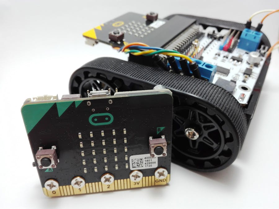
The Micro:bit is an ARM-based embedded system designed by the BBC for use in computer education in the UK, But it is currently available in other countries of the world.
The board is 4 cm × 5 cm and has an ARM Cortex-M0 processor, accelerometer and magnetometer sensors, Bluetooth and USB connectivity, a display consisting of 25 LEDs, two programmable buttons, and can be powered by either USB or an external battery pack. The device inputs and outputs are through five ring connectors that are part of the 23-pin edge connector.
The Micro:bit was designed to encourage children to get actively involved in writing software for computers and building new things, rather than being consumers of media.
In this tutorial, we'll build a simple remote control car (without programming knowledge) with Micro:bit for kids. At the end of this tutorial, our robot will be as follows.
To connect the motors to the Micro:bit, it requires an interface, In this tutorial, we use Elecfreaks Motor:bit.
The Motor:bit has integrated a motor drive chip TB6612, which can drive two DC motors with 1.2A max single channel current. Motor:bit has integrated Octopus series' sensor connectors. You can plug various sensors into it directly. Among these connectors, P0, P3-P7, P9-P10 support sensors with 3.3V power voltage only; P13-P16, P19-P20 support 3.3V or 5V sensors. You can change electric level by sliding the switch on the board.
- TB6612 Motor Drive Chip with 2 channels DC motor connectors, max single channel current is 1.2A.
- Motor speed control with PWM.
- VCC 3.3V/5V electric level switch for P13, P14, P15, P16,P19, P20, this Pins support electric level switch between 3.3V and 5V.
- Buzzer (controlled by P0 pin)
- Support GVS-Octopus electric Bricks connector.
- Input Voltage: DC 6-12V
- Dimension: 60.00 mm x 60.10 mm
For more information, visit the Elecfreaks site.
Assemble the chassisFor convenience, we used a Pololu Zumo Chassis that is made by Pololu. Read the assembly instructions.
After assembling the chassis, the motors' wires need to be connected to the Motor:bit board. Two motor input connectors in total. M1+, M1- and M2+, M2- separately controls a channel of DC motor.
P8 and P12 relatively controls the rotating direction of M1 and M2; P1 and P2 control motor speed.
Do this according to the below pictures. If later uploading codes on Micro:bit, was wrong for rotation of motors, you can easily change the wires of each motor.
At the end it is needed, connect the battery wires to the Motor:bit board. I used two lithium batteries, which provides more power (About 8 volts).
You can control the car in two ways:
- Control via phone mobile phone
- Control via another Micro:bit
In this way, you need to install the micro:bit blue application on the android phone.
Then upload the following code to the micro:bit as receiver and connect the micro:bit to the Motor:bit board.
https://makecode.microbit.org/_XKYHcVYxv83X
Now, you need to pair the phone and the Micro:bit, then control the car through the mobile application.
Example #2: Control via another Micro:bitThis method requires another micro:bit as controller. With the help of Elecfreaks Power:bit, the micro-bit will turn into portable mode and you can easily get it everywhere. It is powered by two 2025 or 2032 button batteries and carries a buzzer on the board. Screw it to the micro:bit and enjoy it!
For the controller, the following code must be uploaded to the micro:bit as sender.
https://makecode.microbit.org/_7kP6WmF3id8m
Then upload the following code to the micro:bit and connect the micro:bit to the Motor:bit:
https://makecode.microbit.org/_Xzf9C85KYFv6
Now, control the car through the micro:bit. When you push A and B keys simultaneously and move the micro:bit forward/backward, the car moves forward/backward. This is done through the gyroscope sensor. To move left or right, just press one of the keys.
I suggest watching the below video:


Comments
Please log in or sign up to comment.