UPDATE 18-09-2018: don't connect motor ground directly to Arduino using a diodo like shown below. I will update this project using an opto coupler for that task. More info here.
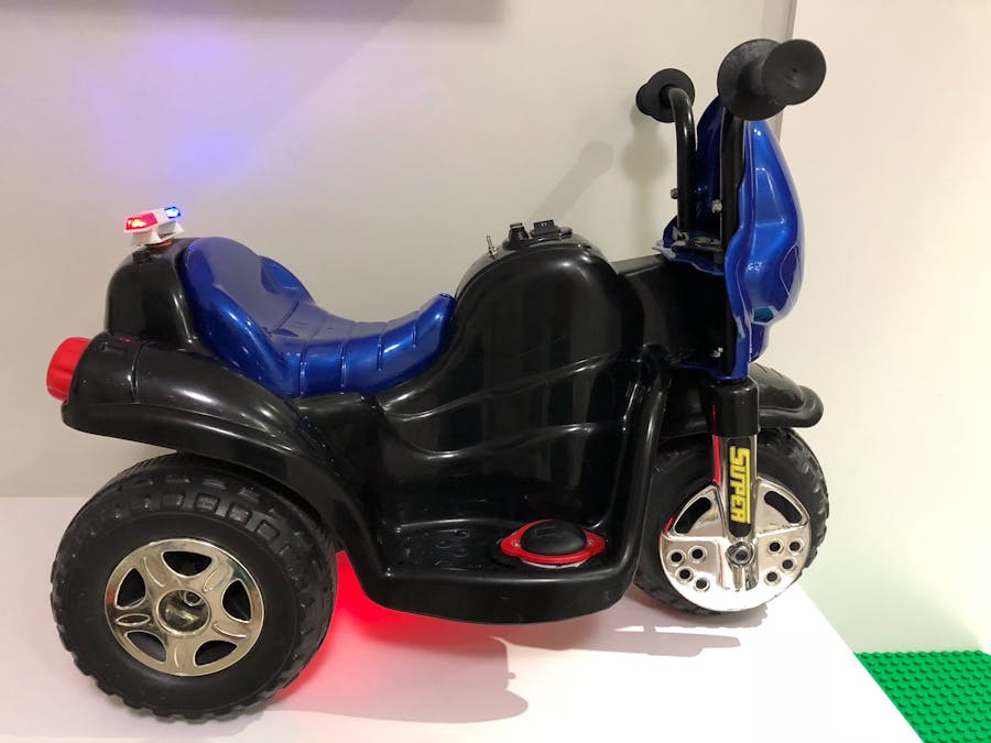
My kids love their electric bike but they would love it even more with a police siren. So I decided to start playing with Arduino and made my first project: it's called Motoca.
Original bike had forward/reverse control and 2 push buttons for pre-recorded audio playback (honk the horn and bike start sound effect).
I got rid of all original electronics including speaker, lead-acid battery and buttons (including the 3 position rocker switch). I kept the 6V DC motor and the original powertrain wire harness (had to do some rewire though).
With some planning and creativity I ended up with the following features:
- new ON/OFF switch for electronics automatically triggers startup sound (no more button for that)
- rear proximity sensor automatically enabled when reverse is engaged
- police siren with 3 modes (lights only, quick siren, loop mode)
- horn (or ability to play other sound effects/music)
- bottom led strip for "fast and furious" mode
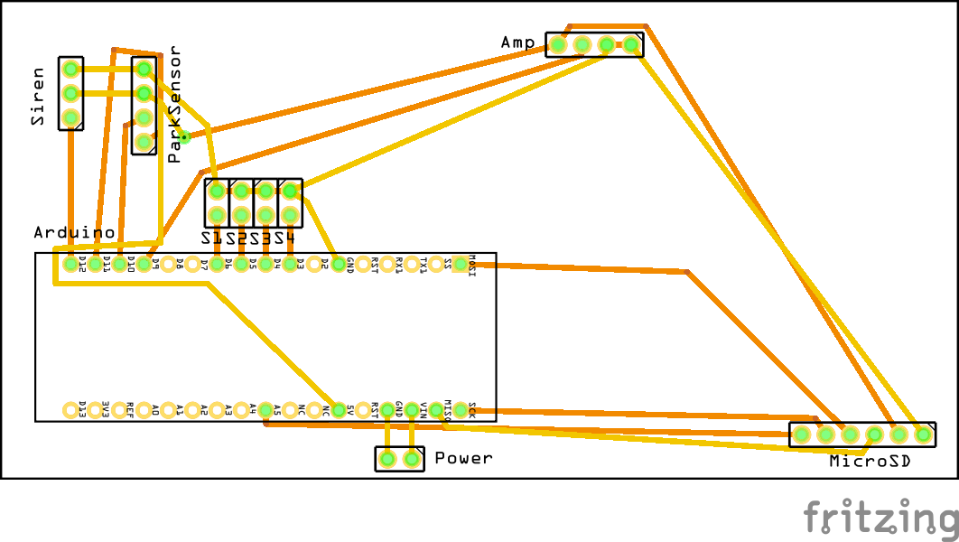
Having all features in mind it was time to design the PCB and order required parts. A mono audio amplifier was needed to drive the new speaker. For audio file storage we are using a MicroSD card module.
The police LED lightning system comes from RC car toys. It's supposed to work with servo protocol but after some tinkering I could manage to make it work with standard Arduino functions.
For the PCB I found 10cm x 5cm a perfect fit for our bike electronics bay. All connections to external modules and wires are made thru pin headers (males or females, straight or right angle). Blue wires are external jumpers in the top of the board while copper wires are soldered track on the bottom.
Connections done as follow (from top to bottom, left to right):
- 3 vertical male pins, straight: police LED flashing system
- 4 vertical male pins, straight: parking sensor
- 4 series of 2 vertical male pins, straight: horn BT, siren BT, reverse signal, siren SW
- 4 horizontal female pins, straight: audio amplifier
- 2 horizontal male pins, straight: power source (Vin and GND)
- 6 horizontal female pins, right angle: MicroSD module
Early stages of PCB (bottom part)
Early stages of PCB (top part), button connections were swapped later
There is no need to connect the LED strip to the Arduino board, so the second mini switch is connected directly to the power train line (switch cuts Vcc).
Talking about power, it was necessary to have 2 power lines (while sharing the same ground) separated: the one I call the power train power line (for DC motor and LED strip) and the electronics power line (for motor cooling fan, Arduino and it's modules). The first one is powered by a 6,6V 2S LiFe battery and the later is powered by a 7,4V 2S LiPo battery (or anything else in the range of the UBEC). The 3 function switch with UBEC lies in between the battery and the electronics power line and is set to regulate output voltage to 5,2V.
Please note that although I have made header pins for Arduino's Vin and GND, they are unused. Arduino power comes from a micro USB cable routed to under seat compartment because electronics power line delivers only 5V (plugging it to Vin would cause Arduino's own regulator to drop voltage even more and the other modules would starve). This has the benefit of making easier software updates: just unplug the USB from below the seat and plug into your computer.
The original 3 position rocker switch (Forward/Off/Reverse) was replaced for a 2 position rocker switch (Forward/Reverse). I had to do some rewiring to be able to signal Arduino when reverse is selected. This is done by tapping into the ground wire of the reverse position in switch and connecting it in the reverse signal pin in our PCB. I also added a diode so we don't harm our Arduino when this pin is shorted with Vcc (at Forward position).
Many different connectors were used to make custom cables for all necessary wiring. The police lighting system, cooling fan and the LED strip have JST plugs. The power switch has a JST (input) and a servo connector (output). My batteries have XT60 and JST plugs. We also need a female USB to drive power to the Arduino board. Please see the parts list for all parts I have used.
Bear in mind that our DC motor is 6V only but we are powering it with a 6,6V (nominal voltage) battery that can reach more than 7V when fully charged. The extra power can make things very hot at our engine so I installed a heatsink with a 5V fan. The fact it's 5V is the reason why the fan is connected to the electronics power line and not the powertrain. You can see the fan in the middle left of the picture above.
Initially I considered to power the electronics with a 9V battery but adding the fan to this power line depleted the battery in a matter of a few minutes. That's why I replaced it later for a 2S Lipo (properly protected with a lipo bag and a low voltage alarm).
Electronics bay is located under the bike, it's a little tight in there but with patience you can fit everything in place. Speaker is installed in the bay cover (same place as the original speaker). Bay cover is shown resting in the left of the picture above.
From top to bottom: police lightning system, proximity sensor, ON/OFF switch for electronics power line
For the Arduino source code please see the GitHub link.
This project is still under development. There is a lot to improve, some known issues and limitations and also some new features planned ahead. Be advised it's my very first Arduino project, I am not in my field of expertise. Contributions are welcome!


_PnKPri8a6q.jpg?auto=compress%2Cformat&w=48&h=48&fit=fill&bg=ffffff)


Comments
Please log in or sign up to comment.