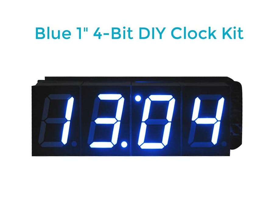
This 4-bit digital alarm clock is based on an AT89C2051 MCU with USB 5V power supply, and features with two-way alarm clock function, hourly chime (8:00-20:00), precise time, and memory function after powered off.
Let's start the soldering.
Schematic Circuit DiagramNotes of installation: The third digital tube DS3 should be installed inversely (the decimal point should be up.
Soldering Steps1. Solder top board
1) Solder 8 resistors.
2) Solder male pin h (solder the short part of the pin header with the top board together. And the long part stays in the outside and connects with the female header with the BOT board).
3) Install the two screws and copper cylinders on the left. (You should tighten the screws now, because you can not do that after installing the digital tube.)
4) Solder the digital tube (the dot on the third bit of digital tube is up) and the touch switch.
2. Soldering BOT board
1) Solder resistors and diode.
2) Solder capacitance, crystal oscillator, base.
3) Solder female pins, transistor, and buzzer.
Put the top board and bot board together and use nut to fix them.
When powered for the first time, the buzzer will sound for quite a while. Use tweezers to make the RET (the manual reset end) of BOT have short circuit and then the clock will work normally (the red circle in the picture).


Comments
Please log in or sign up to comment.