In this article I want to tell you about my DIY logical probe - uProbe.
It is simple enough because it is based on a microcontroller.
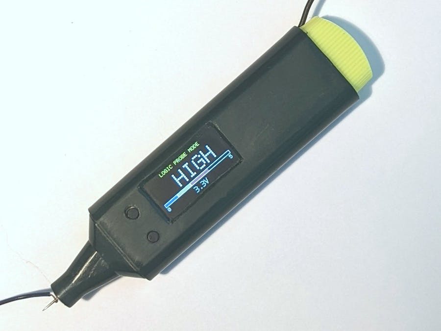
As you can see from the photo, this probe is assembled in the case of highlighter pen, so it is very compact. It does not require an external power source, because it is powered from a Li-ion battery.
This probe is controlled by two buttons.
Charging the battery and updating firmware are done using a special connector, hidden under a highlighter cap.
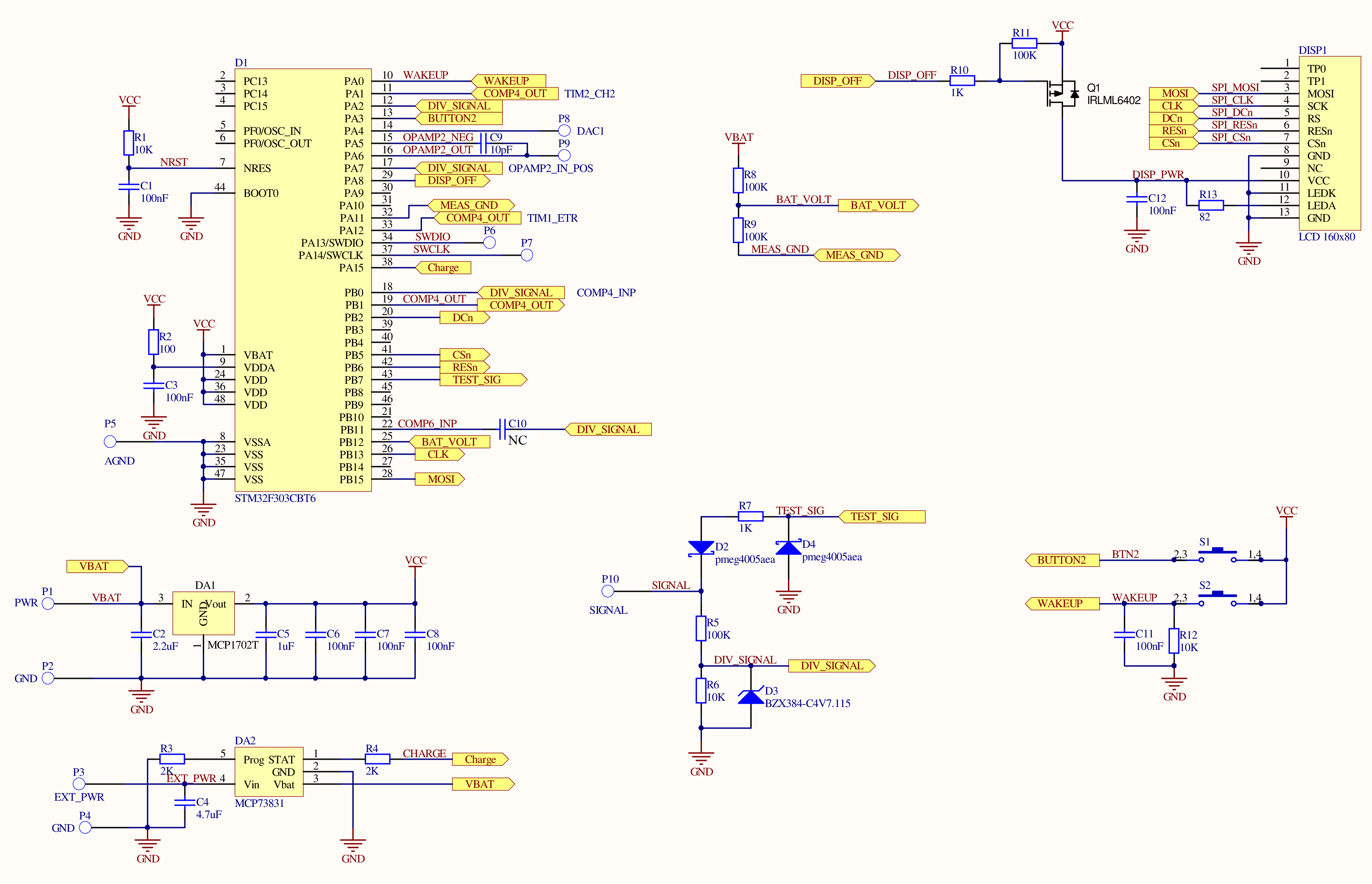
SchematicYou can find the schematic at the end of the project.
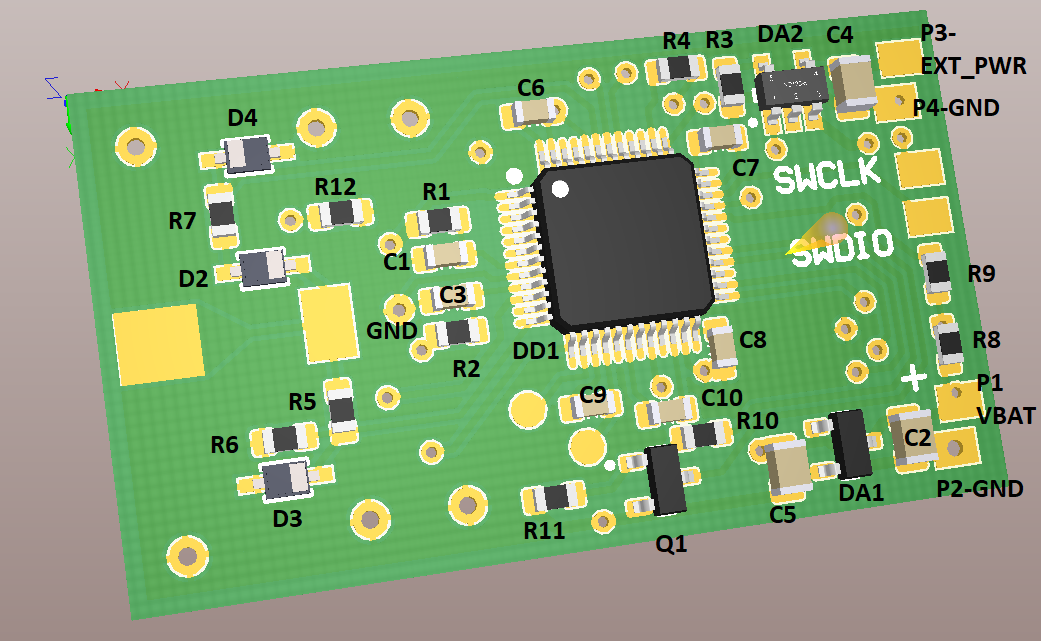
As you can see, the main components at the PCB are STM32F303CBT6 MCU and a small IPS 160x80 0.96" LCD.LCD is powered through Q1 transistor - to minimize power consumption is a sleep mode.DA2 IC is a 3.3V voltage regulator.DA1 IC is a Li-ion battery charging controller.R8/R9 is a circuit for measuring battery voltage. R9 is connected to the GND inside the MCU when voltage measurement is needed.
Parts for input signal conditioning are placed at the center-bottom of the schematic. R5/R6 form a voltage divider, D3 Zener diode is protecting MCU input (but limiting bandwidth).R7 and D4 form a circuit for transferring 100 Hz pulsed signal from the MCU to the input of the probe. This signal is needed for detecting Z-state at the input of this logic probe.This probe can measure voltage in a range 0-30V. Negative voltages can't be measured, but they are not dangerous for the probe (-30V tested).
Modes of operationModes of operation are switched cyclically by lower button - S2.
Mode 1 - logic probe mode
Type of the signal is displayed at the center of the screen:
- LOW - all voltages below 1V
- HIGH - all voltages above 2V
- Z-STATE - when MCU is detecting that there is no external current.
- PULSE - pulsed signal detected
- UNKNOWN - MCU can't detect type of the signal
Color bar below is displaying current voltage, maximum of the bar is 5V.Measured voltage value is displayed below.
Mode 2 - voltmeter mode
Measured voltage value is simply displayed here with a big font.uProbe is not generating additional pulses at its input in this mode.
Mode 3 - frequency measurementmode
Additional hardware modules of the MCU is used in this mode - comparator for input signal digitizing and DAC for defining threshold level of the comparator. Digital signal from the comparator is routed to the ETR input of the timer TIM1.
MCU is measuring time while TIM1 is counting from 0 to 0xFFFF and the value of this time is used to calculate frequency of the signal.
If 0xFFFF is not not reached during 1 second, the number of counted pulses will be used to calculate frequency. There is no quartz oscillator in this device, so frequency measurement is not high.
This probe is working only with positive-voltage signals, so you will need to set the proper value of the comparator threshold (it is displayed at the bottom of the screen). You will need to press the upper button (S1), and the probe will measure and analyse input voltage during one second. Average value of the signal will be used as the new threshold of the comparator.
Mode 4 - UART baudrate measurement mode
This mode is used for measuring speed of the different UART-based interfaces. MCU comparator is used here for generating MCU interrupts at falling edges of the input signal. MCU is saving accurate time value to the buffer at every interrupt. This data is analysed after 128 measurements. Minimal difference between two measurements is used to calculate baudrate. Measured value is rounded to the closest constant standard value.
This algorithm can work wrong at certain conditions (like UART data is all zeroes), but usually it works fine.
Mode 5 - slow oscilloscope mode
The "oscilloscope" mode here is really slow, because I decided that the main task of the probe is to display the presence of pulsations of the input signal.The screen of the probe is too small for more complicated tasks and only two buttons is too low for comfortable control.
The step Y-axis grid and the total range of displayed values are displayed on the screen in the upper right corner. The maximum displayed range is selected automatically, by the maximum value of all those present on the screen. The minimum range is 3V, and the maximum range is 30V.The yellow dots on the grid represent time intervals of 1s.
The measurement principle is the following: MCU takes 1000 measurements with 10KHz sample rate every 100ms. The measured values are analyzed - the MCU determines whether the signal is stable or not. For a pulse signal the minimum and maximum voltages are determined. "Stable" values are displayed with white dots; values containing only one signal transition are displayed with a white vertical line, pulse signals are displayed with a dotted green vertical line.
Pressing the upper button (S1) turns on and off the pause mode - data capture stops in it.
Mode 5 - settings mode
Several items of the menu are displayed here. Cursor can be moved by pressing the upper button. Long pressing the upper button is needed to enter the sub-menu. Long pressing lower button is needed to exit from the sub-menu.
- INFO sub-menu - used for displaying firmware info and the battery voltage.
- CALIBRATE ADC sub-menu - used for starting ADC calibration. You need to apply constant known voltage to the input of the probe for 1 second, and then set that value at the display, using two buttons of the probe.
- SET OFF TIME - set time of automatic probe power off in seconds.
- RESET - reset the probe.
Some information about assembling this probe.
"Faber-Castell Textliner 48" is used as a case for uProbe. It is getting narrow to its writing part, so this must be taken into consideration during PCB development.There are two flanges at each round edge inside the case, PCB is inserted between them.
You can glue a special paper mask to make easier cutting holes for the buttons and the display (you can find the mask at the GitHub):
I recommend soldering the buttons to the board only after the holes for them have been drilled. At first you have to solder only by two pins out of four at each button - in this way it would be easier to move the button if it turns out that it is not exactly where you want it to be.
Usual sewing needle is used here, it is simply soldered to the PCB. Its length is 38mm:
The needle has a special flat protective plastic plate on it, it will be described below.
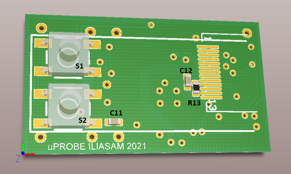
This is how the PCB looks like from the screen side:
You can see that the connector (for programming and changing battery) on the right side is glued to the battery. A gasket of some soft material should be glued between the screen and the PCB. It is needed to press the screen to the case of the probe.
On the back side of the probe, under the buttons, there is a hole in the case, into which a screw is screwed. This screw is pressing the PCB to the top flanges of the case and prevents it from moving when the buttons are pressed. To prevent the screw from damaging the board, it is necessary to have a protective plate.
To prevent the needle from bending when you press it, I inserted a metal terminal from an old glass fuse with a diameter of 5 mm into the hole in the writing part of the highlighter, and drilled a small hole in this metal part.
Video with examples of using uProbe (with English subtitles):


Comments
Please log in or sign up to comment.