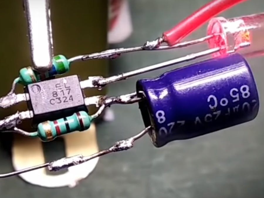
LED Flasher is a simple electronic project made by using basic electronic components like a photocoupler (PC817), resistors, a capacitor, and an LED.
The LED flashes with a small delay. For this, the theory called the RC time constant is used. You can see a simple circuit diagram for the RC time constant in the below image:
In this theory, it says that when a capacitor and a resistor are connected in series with a power source, it takes a constant time depending on the values of the resistor and the capacitor. With this charging time, a current will be flown through the resistor and when the capacitor is charged, no current flow will occur. And then, it will remain like this until the capacitor is discharged. Then, a small current will flow and charge the capacitor. This process will happen continuously if power is supplied. When the current is flowing through the capacitor and resistor connection point, it will be nearly 3V and when the current is not flowing, it will be equal to ground. This means that this point is switching high and low every constant time period.
Let's say we need to build a flasher with a flashing time of one second. We can calculate this using the RC time constant equation:
τ = RC
Here, τ indicates the RC time constant. R indicates the resistance and the C indicates the capacitance. By using this equation, we can calculate that if we use a 5.6kΩ resistor and a 220µF capacitor, we will get a 1.2S RC constant. Which means that we can build an LED flasher that flashes every 1.2 seconds.
Circuit DiagramThis is the basic circuit diagram of the LED flasher. The positive lead of the 3.7V battery is connected to the positive lead of the LED and the 5.6kΩ resistor. The 5.6kΩ resistor and the 220µF capacitor is forming the RC circuit we talked about before. The capacitor and resistor connection point are connected to the anode of the PC817 optocoupler which means that the PC817 anode pin will switch high and low every 1.2 seconds. In this circuit, the R1 resistor has two purposes. The first one to limit the current to the LED. The second purpose is to discharge the capacitor when it is charged. When this oscillating signal is given to the anode pin of the PC817 from the RC circuit, the photodetector will trigger according to the signal and control the LED accordingly.
Steps to follow:Step 1: Arrange the components.
Step 2: Solder the 1kΩ resistor to the second and third pin of the PC817 optocoupler.
Step 3: Solder the 5.6kΩ resistor to the PC817 optocoupler.
Step 4: Solder the 220µF capacitor to the third pin of the PC817 optocoupler.
Step 5: Solder the LED to the circuit as shown in the circuit diagram.
Step 6: Connect the battery terminals to the circuit.
Now that our circuit is ready, the LED should flash every 1.2 seconds.
How it works:1. When the capacitor charges, it sends a high signal to the anode pin of the optocoupler causing the PC817 to turn on the LED.
2. When the capacitor is fully charged, the current flow will stop and the anode of the PC817 will be equal to ground. This will cause the LED to turn off.
3. The capacitor will discharge in the meantime.
4. When the capacitor is fully discharged, it will begin to charge again to turn the LED on.
5. The process repeats as long as power is connected to the circuit.
Please watch this full video for more information:
ConclusionThis circuit can be used as a night indicator light. This will work months from a single 3.7V lithium battery. The flash time can be adjusted using the equation given in the tutorial.
Enjoy! Contact us for any inquiries!


Comments
Please log in or sign up to comment.