Credits go to educ8s.tv on YouTube:https://youtube/u4bdmXqppB8
This project is one of the easiest for any maker. It includes a PIR (Passive Infrared) Motion Sensor which is a common sensor used for motion detectors. Security systems, burglar alarms and home automation projects will include this at some point. With building this simple sensor circuit, you can add on to this to make a more advanced system. This tutorial's parts needed are:
- 1 Arduino (the Keyestudio Uno is used in this example)
- 1 PIR Motion Sensor
- 3 Jumper Wires (Male to Female)
- 1 LED (any colour)
- 1 USB Data Cable (depends on the Arduino)
Please visit this link here for NextPCB's special offers.
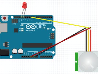
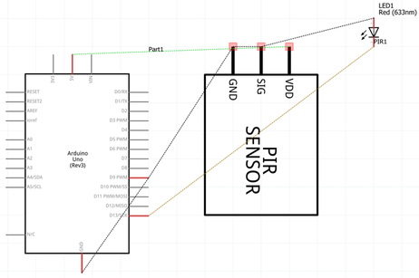
Now, that you know a little bit about this project, let's begin with the hardware side. Remember to always unplug the power supply and disconnect any circuits from the current Arduino board. First of all, plug all three female pins to the PIR Motion Sensor. Then, connect the positive (+) pin of the sensor to 5v (+5 volts) of your Arduino, the ground (-) pin of your sensor to GND (-) on your Arduino, and the output pin of the sensor to the D9 (digital pin 9) on your Arduino. Next, connect a LED with the cathode leg going to the GND (-) on your Arduino and the anode of the LED to D13 (digital pin 13) on your Arduino. Once all of the connections have been done, you are ready to go onto the software side of this project.
About the codeThe code is very easy to read because it uses an easy language and easy writing to understand. The first three lines of the Code starts with declaration of variables from hardware such as the LED uses pin 13 and the PIR Sensor uses pin 9. The value uses pin 0 because it is the receive pin. Next, is the usual void setup which indicates the first part of the Code, that describes the LED as OUTPUT (off). It also means the PIR Sensor is INPUT (on). Lastly, the void loop phrase loops the value first as we've mention in the beginning. Value in this line means that it will read the PIR Sensor and give information to the microcontroller on the next step in the process. The last line is the last step and will be repeated with the second last line. Our main line is the last line because it outputs the whole code and reacts to the information its given, the LED is turned off.
Amazing opportunitiesUTSource.net Reviews
It is a trustworthy website for ordering electronic components with cheap price and excellent quality.
Also, be sure to check out PCBWay, a leading manufacturer and distributor in PCB design and manufacturing. They have amazing prices and excellent quality in their services, so don't miss out on them! Plus, PCBWay has an amazing website, online Gerber viewer function and a gift shop so make sure to check out their links below:
PCBWay Free Online Gerber Viewer Function: https://www.pcbway.com/project/OnlineGerberViewer.html
PCBWay Gift Shop: https://www.pcbway.com/project/gifts.html
Make sure you check out the review for this meter by clicking here.
Enjoy! Contact us for any inquiries!


_ztBMuBhMHo.jpg?auto=compress%2Cformat&w=48&h=48&fit=fill&bg=ffffff)


Comments
Please log in or sign up to comment.