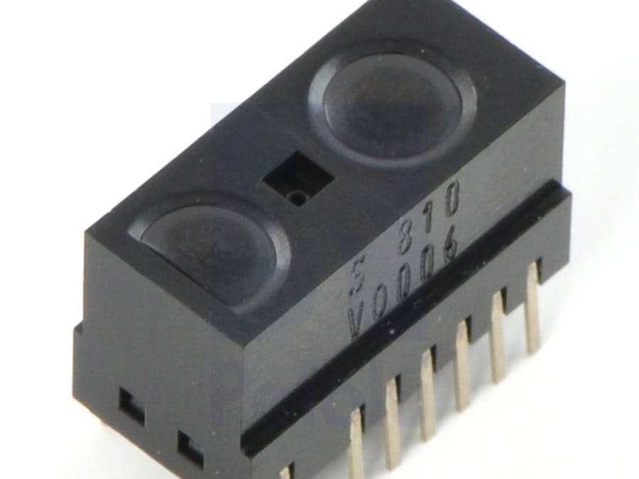
Sharp distance sensors are usually used to measure distances: depending on the product, this can be between 2 cm and 5 m.
In my case I had the product GP2Y0D810Z0F at hand and had to jump over 2 hurdles. My contribution here describes my experience.
The GP2Y0D810Z0F belongs to the family of two other sensors: the GP2Y0D815Z0F and GP2Y0D805Z0F.
Germans can buy here in ebay-Store.
These sensors come with and sometimes without a breakout board.
Only the naked sensor was available to me and so I acquired a so-called "Carrier Board" (Pololu # 1133). The first hurdle was easy to take by 2-3 euros. The website of Pololu provides information on which side to set the solder points: the sensor has to lie flat on the PCB. On the side of the existing components, the solder points for the PINs of the sensor are attached. There are 2 PIN headers with 3 PINs each for the Carrier Board packet: straight and curved, so that you can fit the sensor into your project later on. GND, VCC and signal are to be created as usual.
The Carrier Board also brings a lot of comfort: a red LED lights up as soon as an object is detected within the distance of 2 - 10 cm from infrared (= low). Outside this measurable range, the LED goes out (= high). If the LED bothers you can disable the LED with a cut. More about this on the Pololu-Schematic.
I then learned how important it is to read the data sheet or at least the product description: instead of obtaining different analogue input voltages and then converting them into distances using a mathematical formula, this sensor delivers "low" in the measuring range (2 - 10 cm ) and otherwise "high" outside this range. Visually, this is supported by the red LED of the carrier board.
This means you can still connect the sensor to the analog port, but also on the digital port.
"Note that these sensors will only tell you if there is an object within the detection range along their lines of sight; they will not tell you how far away the object is.", source.
The square pad is ground, the middle pad is VIN (2.7 – 6.2 V), and the remaining pad is the sensor output, OUT. Depending on your power source, you might notice an increase in performance by placing a large (>10 uF) capacitor between power and ground somewhere near the sensor.
Thats all you need:
void setup(){
Serial.begin(9600);
}
void loop(){
Serial.print("Digital Signal:");
Serial.println(digitalRead(3),BIN);
delay(50);
}
You can play a bit around with this:
int IRpin = 0; // Analogeingang
double value, volts;
void setup()
{
Serial.begin(9600);
}
void loop()
{
value = analogRead(IRpin);
volts = value*5.0/1024.0;
Serial.println(volts);
delay(50);
}


_ztBMuBhMHo.jpg?auto=compress%2Cformat&w=48&h=48&fit=fill&bg=ffffff)


Comments
Please log in or sign up to comment.