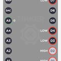
Today we discuss Voltage Level Shifter - on my desk is a model with prefixed A and B letters on the otherwise familiar abbreviations such as VCC (+), SCL, SDA (for I2C signal transmission) and GND (-). It is a 5-3V System I2C Level Converter module.
Feature: Compatible with 5-3V system for sensor.
AVCC connect to 5V system powerASCL connect to 5V system SCLASDA connect to 5V system SDA AGND connect to 5V system GND
BVCC connect to 3V system powerBSCL connect to 3V system SCLBSDA connect to 3V systems SDABGND connect to 3V system GND
The first test documents exactly this structure without consideration of SCL and SDA. It's not about transmitting data, but checking the output voltage.
Case 1Via USB, 5V voltage is supplied to a breadboard via the power supply.
Following the documentation, a 3.3V output is generated with 5V input to AVCC to BCC. This works and was so expected.
Case 2In the next attempt we turn the converter and supply 5V voltage to BVCC. What voltage will probably be output to AVCC?
AVCC will output 4.6V voltage. A reduction to 3.3V does not take place here.
What happens if we apply 3.3V to the breadboard via the power supply to both the AVCC and BVCC?
In the third experiment, 3.3 volts are supplied to AVCC and 3.18 volts are output to BVCC.
A similar picture with 3.25 volts output voltage to AVCC, provided we supply voltage to BVCC 3.3 volts.
In summary, the Voltage Level Converter works correctly when switching from a higher 5 volt input voltage (represented by letter A) to a lower 3.3 volt output voltage (represented by letter B).
If your connected sensors do not output any values as expected, the orientation of your converter will be checked!


_3u05Tpwasz.png?auto=compress%2Cformat&w=40&h=40&fit=fillmax&bg=fff&dpr=2)
Comments
Please log in or sign up to comment.