I3C® (Improved Inter-Integrated Circuit) is a new serial protocol from the MIPI® Alliance. I3C operates faster than I2C while adding new features such as Common Command Codes (CCC), In-Band Interrupts (IBI), Hot Join and Dynamic Addressing. Like I2C, I3C is normally a two-wire bus (the exception is not relevant for this example). A video overview of I3C is in the video below; a copy of the I3C specification is available from the MIPI Alliance here.
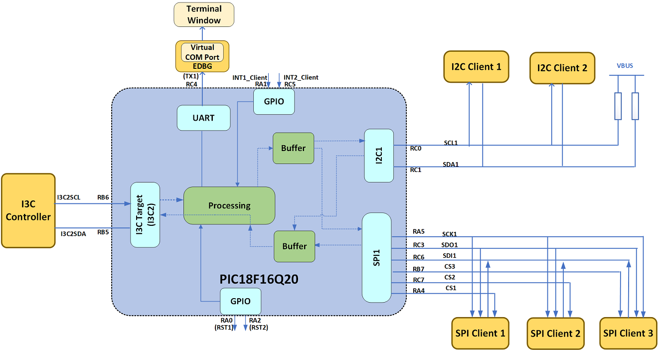
One of the challenges developers may face with I3C is connecting to SPI or legacy I2C devices. While there is some native I2C support in I3C, it requires the I2C device to follow a specific set of characteristics, which may not be possible from the desired device. Another way to interface with these devices is via the PIC18F16Q20 family of microcontrollers. It operates as an I3C target and can act as a communication bridge between I3C, SPI and I2C buses. The code example developed can perform the following actions out-of-the-box:
- Read/write to I2C bus and up-to 3x SPI devices.
- Notify the I3C controller of interrupts from these devices with In-Band Interrupts (IBI).
- Generate 2 RESETs for connected devices.
- Supports a maximum of 500 bytes of data on I2C/SPI bus.
Full implementation details and the source code are available here.
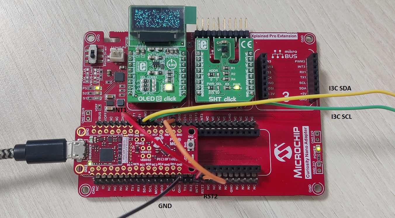
To implement this code example, a Curiosity Nano Adapter (AC164162), a PIC18F16Q20 Curiosity Nano Evaluation Kit (EV73T25A), an OLED B Click and a SHT Click were connected as shown.
In this configuration, the microcontroller runs at a voltage of 3.3V, but the I3C bus runs at 1.2V by using special Multi-Voltage I/O (MVIO) pads inside the microcontroller. Other I3C bus voltages are possible by disconnecting the built-in 1.2V supply used (see the original example for more details).
The SHT Click measures temperature and humidity and communicates over I2C, while the OLED Click displays image data and communicates over SPI. In this configuration, the sensor can be configured for periodic measurements of the ambient conditions, with an interrupt generated if the conditions exceed a programmed setpoint. If this occurs, the bridge will transmit an IBI to the I3C controller to alert it of the condition. The OLED B Click is used to display arbitrary data from the controller on its display. Two jumper wires are used to bridge the reset and interrupt lines for socket 2.
Software for this example was developed in MPLAB Code Configurator (MCC). MCC is a graphical tool that allows users to easily implement and utilize the hardware peripherals inside the microcontroller.
Concluding ThoughtsI3C is a powerful new serial communication standard. However, connecting to other devices can be tricky, so a communication bridge may be needed. A PIC18F16Q20 microcontroller can be configured to perform this action, and since the microcontroller acts as a generic bridge, any other SPI or I2C sensors could be used in place of these parts by changing the data sent by the controller.
Additionally, the functionality of the microcontroller and the communication the microcontroller expects can be modified to fit the application by adjusting the software. For instance, if the sensors were known constants, the microcontroller could offload some of the generic communication work to reduce the amount of traffic on the I3C bus.
Irene Abraham


Comments
Please log in or sign up to comment.