
_MxyXikZ64k.gif?auto=format%2Ccompress&gifq=35&w=400&h=300&fit=min)

Hardware components | ||||||
 |
| × | 1 | |||
Hand tools and fabrication machines | ||||||
 |
| |||||
Many vocalists and choirs use chromatic pitch pipes, which are essentially chromatic harmonicas, to find their starting pitch before a song. They simply blow into one of the 12 pitch holes on the pipe (There's an extra 13th hole to play an octave higher than the lowest note) to hear their selected pitch and the choir tunes to that note! Find a typical pitch pipe below:
Some vocalists and musicians have even trained their ears so acutely that they have developed "perfect pitch". Meaning they can accurately sing any note on command!
OverviewIn this project you will learn:
- Introductory to intermediate python programming concepts
- How to use the microphone, speaker and Neopixel LEDs on the Circuit Playground Express
- How to edit an existing .stl (3D file)
- How to 3D print an enclosure for the Circuit Playground
- To develop your pitch training skills! (If you practice hard enough you might be able to develop relative pitch or even perfect pitch)
Music Theory 101
In traditional music theory there are 12 different pitches in a given octave. For example from the bottom C to the top C on the piano below is one octave. If you count the keys from C to B, you get 12. 7 white keys and 5 black. So why do the black keys have 2 different names? Aren't they the same pitch? Yes indeed they are however they have two different names. A pitch with two different names is called an enharmonic. One reason you might see one over the other is if the song or melody is in a specific key. For example if you were playing in the key of G, you would call the 7th note in the G major scale F# rather than Gb.
One last note (pun intended 🤓), the notes E#, Fb, B#, and Cb, the invisible notes in between the white keys with no black keys, are rarely recognized as notes in music so we won't worry about them for the purposes of this project. If this question interests you learn more about it here.
In this project you'll be able use your Circuit Playground Express as a digital pitch pipe. Thanks to the Circuit Playground Express's built-in microphone sensor, buttons and Neopixel leds, all you have to do is upload the code and it works!
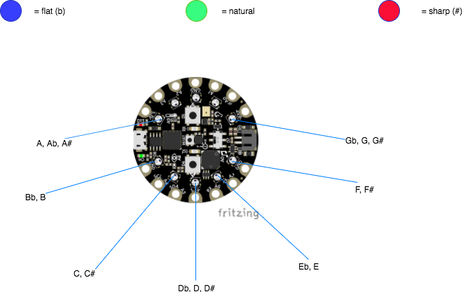
- We'll be using seven of the ten neopixels to represent each pitch.
- Use the up and down buttons to move up and down pitches.
- Once a pitch is selected, blow into the Circuit Playground and hear your pitch!
- Blue means the note is flat, green means natural and red is sharp.
In the example below, Bb is selected and sounded.
If this is your first CircuitPython project or you are new to Python or even coding, no need to worry, I've included the steps needed to go about setting up the Circuit Playground Express with CircuitPython, and a step by step process of how the code works. If you're wondering, CircuitPython is a variation of the python programming language but optimized for hardware like our Circuit Playground. It was developed by Adafruit.
If you are a CircuitPython expert or already have your board configured for CircuitPython feel free to skip ahead!
Let's get started.
Step 1: Configure Circuit PlaygroundIf you haven't yet configured your Circuit Playground Express to run CircuitPython now is your chance, it's easy! If your board is already running CircuitPython consider updating to the newest version. To run CircuitPython on your Circuit Playground follow this quick and easy set up guide over at Adafruit: https://learn.adafruit.com/adafruit-circuit-playground-express/circuitpython-quickstart
Step 2: Setting Up a Text EditorIn order to write and edit code, you'll need a text editor. You can use any one you'd like but the easiest editor to use in conjunction with the Circuit Playground Express is called the Mu Editor. It has built in functionality to receive immediate feedback from the Circuit Playground's serial monitor. This means it's super easy to find problems with your code. Follow this short guide over at Adafruit to install the Mu editor on your computer: https://learn.adafruit.com/welcome-to-circuitpython/installing-mu-editor
Step 3: Programming the Pitch PipeI suggest uploading the given code first to test out the program yourself and to make sure the board is working correctly.
To download the code scroll down, grab the file "code.py" and drag it to your CIRCUITPY drive.
I had tremendous help figuring out how to hack this together thanks to two awesome guides Adafruit wrote on using the microphone and speaker. Much of the following code is adapted from these guides so thanks Adafruit!
Note*: Make sure you have the right updated libraries so that the program will function properly. Information on where to find and update libraries: https://learn.adafruit.com/welcome-to-circuitpython/circuitpython-libraries
Once you have the pipe working correctly we'll take a look at the code to see how it all works and so that you can hack it to make something even cooler.
Feel free to open code.py in Mu or your code editor of choice to follow along.
Programming in Python
If you are new to Python, here are a couple of tips to save you the frustration I faced:
- Unlike other programming languages, spacing and tabs in Python are extremely important and are built into how programs are compiled.
- After the first line of an if statement, function, or loop, the following line of code MUST, be indented by a tab.
- DO NOT use spaces instead of tabs or you will be in a world of head ache
- Any extra spaces before lines of code will crash your program and it will not work
- Once I got used to the framework of the language I found I quite like that writing clean and indented code is necessary for the program to function properly.
With that said let’s get coding ⌨️
Importing Libraries
We'll start the program off by first importing the necessary libraries needed to make the program run. They can be imported because they lie in the CIRCUITPY drive in the folder "libraries" as seen above. These libraries will allow us to analyze audio coming into the mic (audioio, audiobusio, and array), control the neopixel leds (neopixel), use the buttons (from digitalio import DigitalInOut, Direction, Pull, board), set times for how long we want the pitch to last (time) and perform various important math functions for calculating sound levels (math)!
import audiobusio
import board
import array
import math
import time
from digitalio import DigitalInOut, Direction, Pull
import audioio
import neopixel
Declaring Variables
Next, we need to declare variables that we may want to change at a later time.
- blowThresshold will be the value of how loud the sound needed to trigger the current pitch.
- debounceTime is how long the debounce time should be to prevent multiple button triggers in one press. Set to 0.2 seconds
- pitchLength, how many seconds we want the note to sound when triggered. Set to 1 seconds.
- pixelBrightness sets how bright the neopixels are. Can be between 0 and 1.
- SAMPLERATE is the number of samples of audio captured per seconds in Hertz. Set to 8000 Hz
- NUM_SAMPLES is how many samples were collecting. We want this to be tiny because the program will be running in a loop when we collect the samples continuously later. We just need to collect a little snippet of audio every time the program loop runs. (More on this later) If our sample rate is 8000 samples per second and we're collecting a 160 samples each time that gives us just 0.02 seconds of audio captured each time (160samples/8000samples/sec)
- The last string of variables are to set up notes to frequency values which are in Hertz. Find frequency values at https://pages.mtu.edu/~suits/notefreqs.html
# Magnitude of sound needed to trigger current pitch
blowThresshold = 5000
# Time needed to debounce button, in seconds
debounceTime = 0.2
# How long the note sounds for, in seconds
pitchLength = 1
#neopixel brightness (Between 0 and 1)
pixelBrightness = 0.05
#sample rate
SAMPLERATE = 8000
# how many samples we're collecting
NUM_SAMPLES = 160
#frequency values
Ab3 = 208
A3 = 223
As3 = 233
Bb3 = 233
B3 = 247
C4 = 262
Cs4 = 277
Db4 = 277
D4 = 294
Ds4 = 311
Eb4 = 311
E4 = 330
F4 = 349
Fs4 = 370
Gb4 = 370
G4 = 392
Gs4 = 415
Set up the neopixels, buttons, and speaker
- The neopixel leds need to be initialized so we can use them later when we program the the different colors and modes. This is where the brightness of the pixels is set but we can change the value from the top of the program because we made a variable for it!
#set up the neopixels
pixels = neopixel.NeoPixel(board.NEOPIXEL, 10, brightness=pixelBrightness) #determine brightness (Value can be between 0 and 1)
- Next we initialize the buttons on the board by creating two variables, one for each button, and declaring each button as an input. One will be for moving down pitches (buttonD), one for moving up pitches (buttonU)
#
# Program the two buttons on the board to be able to move up and down pitches
#
buttonD = DigitalInOut(board.BUTTON_A) #button a is the down button
buttonD.direction = Direction.INPUT
buttonD.pull = Pull.DOWN
buttonU = DigitalInOut(board.BUTTON_B) # button b is the up button
buttonU.direction = Direction.INPUT
buttonU.pull = Pull.DOWN
- Next we initialize the speaker on the board and declare it as an output.
#
# enable the speaker
#
spkrenable = DigitalInOut(board.SPEAKER_ENABLE)
spkrenable.direction = Direction.OUTPUT
spkrenable.value = True
Receiving and analyzing input from the microphone
- First we initialize the mic and give it a variable so we can access it later. This is done through something called PDMIn. PDM is the type of microphone we're using.
- In order to record samples of audio later we need to prepare a buffer of sorts to record that audio into. We will make a blank array called samples that will later be filled with values from our microphones input.
# Prep a buffer to record into
mic = audiobusio.PDMIn(board.MICROPHONE_CLOCK, board.MICROPHONE_DATA, frequency=16000, bit_depth=16)
samples = array.array('H', [0] * NUM_SAMPLES)
- Next we need to create a way to calculate the loudness of the sounds coming into the microphone. How do we do this?
Let's look at potential sound that might come into the microphone:
If we zoom in really close it might look like this:
If we simplify the signal a bit and make it a sine wave, we can see the amptitude of the signal over time.
- To find the "loudness" of a sound we need to find the amplitude of the signal
- We can calculate the amplitude of one peak pretty easily, but how do we find the average the amplitude of all the peaks in a signal?
- Well there are a couple ways:
Peak to peak will give you the average maximum of the peak values but unfortunately is not as accurate because of irregularities in the samples.
Root means square is a better method of calculating the average amplitude of a sound because it throws out the irregularities in the samples.
- Here is a great resource that explains how root means square works and how it is calculated.
- Here are the "user defined functions" we will later use to calculate the rms value of our samples.
# Remove DC bias before computing RMS.
def normalized_rms(values):
   minbuf = int(mean(values))
   return math.sqrt(sum(float((sample - minbuf) * (sample - minbuf)) for sample in values) / len(values))
def mean(values):
   return (sum(values) / len(values))
Create a counter
- We must next create a counter that will track button presses. This counter will let the program know which note should be sounded when blown as well as which neopixel and color should be on.
- We declare the counter outside of the following while loop so that it doesn’t get reset back to 0 at the beginning of each loop.
#Create a counter for tracking button presses
#Declared outside scope of while loop so it doesn't get reset to 0 at the beginnning of every loop!
counter = 0
While loop
- Now that all our variables have been set and our functions defined we can program the main program loop where the actual functionality will be built.
- We want some way to continuously check for noise into the microphone to know when to sound the current pitch.
- We record a short clip of audio into the samples array we created earlier.
- Next we take the RMS of the sample to get our magnitude.
- We have a print statement here to be able to check our magnitude values in the REPL
while True:
   #We begin regcording samples from the board's mic
   mic.record(samples, len(samples))
   magnitude = normalized_rms(samples)
   print("mag = ", magnitude) #print the magnitude of the input blowing so we can track values in the serial console
- Next we will create an if statement to check for button presses and track each press
- We want a button that moves up pitchs and one that moves down pitches
- Each time a button is pressed we will have a new neopixel value so we must reset the other pixels before setting the new one. Pixels.fill((0,0,0)) does exactly that.
- To track button presses we will increment the counter by 1 if the up button is pressed and -1 if the down is pressed
- Lastly we need to “debounce” the buttons. When a button is pressed by a human, it’s actually held down for a tiny amount of time that we perceive as just an instant but is actually several thousanths of a second. Thus with out debouncing the button it will actually get triggered multiple times when pressed.
- To prevent this we debounce the button by adding a short delay of 2/10s of a second after a button is pressed.
   #If statements to know when up or down buttons are pushed
   #We will use a counter to track which pitch is selected
   if buttonU.value == True:  # If Up button is pushed then move up a pitch
       pixels.fill((0, 0, 0)) #turn all neopixels off
       counter += 1 #increase the counter by 1
       time.sleep(debounceTime) #to ensure button isn't triggered multiple times in one press we must "debounce" the button by creating a short delay after pressing it
   elif buttonD.value == True: #Do the same for the down button
       pixels.fill((0, 0, 0)) # If Down button is pushed then move down a pitch
       counter -= 1 #decrease counter by one
       time.sleep(debounceTime) #debounce button
While loop cont'd (setting frequencies for the counter values)
- Now that we’re tracking each button press, we’ll match counter values with pitches and neopixels.
- To do this we create a long if statement that checks for different values of the counter we created. Starting on the lowest pitch, which is Ab, where the counter is initially set to 0, the board will output a blue hue on the 9th neopixel of the board. We will set the frequency variable to that of Ab’s frequency which we declared earlier.
- Imagine the up button has now been pressed. The counter value would now be set to 1. Because we want to go up a pitch to A natural, we say if counter = 1, set the 9th neopixel to green and update the frequency to that of A natural’s.
- We repeat this process all the way until the counter = 16 so that every pitch is accounted for.
- You might be expecting there only to be 12 pitches and there are but the extra 5 are actually the enharmonics of other pitches such as A# and Bb.
   #If statements for determine which pitch the board is on
   #We will use the current counter value to set which frequency, neopixel, and color should be selected
   if counter == 0:  # Ab
       pixels[9] = (0, 0, 255)
       FREQUENCY = Ab3
   elif counter == 1:  # A
       pixels[9] = (0, 255, 0)
       FREQUENCY = A3
   elif counter == 2:  # A#
       pixels[9] = (255, 0, 0)
       FREQUENCY = As3
   elif counter == 3:  # Bb
       pixels[0] = (0, 0, 255)
       FREQUENCY = Bb3
   elif counter == 4:  # B
       pixels[0] = (0, 255, 0)
       FREQUENCY = B3
   elif counter == 5:  # C
       pixels[1] = (0, 255, 0)
       FREQUENCY = C4
   elif counter == 6:  # C#
       pixels[1] = (255, 0, 0)
       FREQUENCY = Cs4
   elif counter == 7:  # Db
       pixels[2] = (0, 0, 255)
       FREQUENCY = Db4
   elif counter == 8:  # D
       pixels[2] = (0, 255, 0)
       FREQUENCY = D4
   elif counter == 9:  # D#
       pixels[2] = (255, 0, 0)
       FREQUENCY = Ds4
   elif counter == 10:  # Eb
       pixels[3] = (0, 0, 255)
       FREQUENCY = Eb4
   elif counter == 11:  # E
       pixels[3] = (0, 255, 0)
       FREQUENCY = E4
   elif counter == 12:  # F
       pixels[4] = (0, 255, 0)
       FREQUENCY = F4
   elif counter == 13:  # F#
       pixels[4] = (255, 0, 0)
       FREQUENCY = Fs4
   elif counter == 14:  # Gb
       pixels[5] = (0, 0, 255)
       FREQUENCY = Gb4
   elif counter == 15:  # G
       pixels[5] = (0, 255, 0)
       FREQUENCY = G4
   elif counter == 16:  # G#
       pixels[5] = (255, 0, 0)
       FREQUENCY = Gs4
- What happens when the counter goes above 16 or below 0?
- Well if we press the up button when the counter is at 16 and the pitch is set to G#, we want it to go back to Ab where the counter = 0.
- Conversley if we're at Ab where the clounter = 0 and we want to go down a pitch to G# we'll have to set the counter to 16.
- To do this we add the statements below.
   elif counter > 16:  # if counter goes above 16 set back to 0
       counter = 0
   elif counter < 0:  # if counter goes below 0 set back to 16
       counter = 16;
While loop cont'd (Triggering the pitch)
- This last chunck of code will tell the speaker to sound the selectected pitch when it hears a loud sound aka your breath!
- We'll say that if the magnitude of the sound is greater than 5000 (value defined earlier) then sound the current pitch.
- Next we create the pitch we want in the form of a sine wave that is created at the desired frequency
- Then we’ll tell the speaker to play the pitch for 1 second.
- Lastly we tell the board to show the current value of the neopixels.
   #If statement to trigger pitch when user blows into mic
   #We will say that on a any loud sound the pitch is triggered
   if magnitude > blowThresshold: #any time we get a sound with a magnitude greater than the value of blowThresshold, trigger the current pitch (can be changed at top where it is defined)
       SAMPLERATE = 8000
       length = SAMPLERATE // FREQUENCY #create length of sample
       sine_wave = array.array("H", [0] * length) #create an array for a sine wave
       for i in range(length):
           sine_wave[i] = int(math.sin(math.pi * 2 * i / 18) * (2 ** 15) + 2 ** 15) #fill the array with values
       sample = audioio.AudioOut(board.SPEAKER, sine_wave)
       sample.frequency = SAMPLERATE
       sample.play(loop=True)  # Play the sample
       time.sleep(pitchLength)  # Play for length of pitchLength
       sample.stop()  # we tell the board to stop
   pixels.show() #show the desired neopixel light up on board
#End program!!!
All done!!
The Serial Console
To see what magnitude values your mic is giving you, use the REPL on Mu. There's a print statement I put in the code that prints the value of the mic magnitude every time the program runs through the while loop. You can print any data you want by creating a statement like this. More on printing output in Python here.
print("mag = ", magnitude)
Click on the REPL button at the top of Mu.
Next you should see a section at the bottom of the editor pop up. This is where your program output will be sent. If you aren't already getting the magnitude values to print, try clicking in the box that just opened up and doing a control + d, this will start the process of outputting the data. If you want to stop the program from outputting the data, do a control + c.
The REPL can be a great resource to help debug your code. If you have errors in your code, the REPL will tell you what's going wrong and where. Handy!
I know, that was a lot... moving on... to 3D Printing!!!
Step 4: 3D Printing the EnclosureTo make the pitch pipe more readable we will make a case with letters A-G that will line up with the 7 neopixels we're using. The case will be 2 halves that snap-fit together and 4 screws that will hold the Circuit Playground in place. No need to order specific screws and wait 3 days for them in the mail, they are 3D printed!
If you don't have access to a 3D printer there is more than likely a maker space or fab lab near you with more 3D printers than they can handle. You can pay a small fee at these places to have them 3D print your files right in front of you! These places also have equipment like laser cutters, a wood shop, and all the maker needs you could ever desire.
Check to see if there's a Fab Lab near you here.
If not there are several companies that will 3D print your parts and mail them to you. Find a good one here.
The parts
Here's what all the parts look like after being printed, along with the Circuit Playground for reference.
The two pieces snap together and the screws hold everything in place!
Designing the case
I designed the case using an existing model created by the Ruiz brothers. Find a link to that original case guide here.
I took the Ruiz Brother's design and added the letters and words with a free online cad software for beginners called Tinkercad. It's seriously easy to use and you don't need any previous experience to learn it.
To edit any existing design, you need an .stl file of the design, which the Ruiz brothers graciously provided. Once you download the .stl file, you can upload the file into Tinkercad and edit it from there!
In Tinkercad you can drag and drop pre-made letters and shapes onto your existing file.
To edit this design, I chose to make the letters holed rather than extruded or sticking out of the case. I did this because when the case is printed, much better results can be attained from the holed letter method as the extruded letters tend to made things more droopy because of overhang. More on that here.
Once you have all your letters and edits in the right place, you can group them altogether which basically cuts the holes where you placed them and gives you one file with everything together.
Select the entire model and all the parts you created and then click "Group" in the top right hand corner.
Designing screws
Originally, this case required metal machine screws of a specific size and type to hold the Circuit Playground Express in place. I didn't have immediate access to these specific screws and didn't feel like ordering them online or scavenging through Home Depot, so I designed my own screws in Tinkercad and 3D printed them myself! (Technically they're more like pegs)
First let's make the basic screw shape by dragging in two cylinders. One for the screw body and one for the top. Edit each part accordingly.
Next, place and group the screw parts together.
Now in a different Tinkercad file, import the case bottom .stl file.
We will use the model to size the screw to and make sure it fits tightly in the holes.
Copy and paste the screw you made into this file. Size the screw so that it fits into any of the holes snugly.
Make sure you leave enough room for the Circuit Playground Express.
Once the screw is sized right and fits in a hole, you are ready to print it!
Save the resized screw into a new file and download the .stl.
And that's it! Download the file and it's ready to be printed!
Preparing the files for 3D printing
Now that we have the files ready for printing, we need to tell what ever 3D printer we are printing on the specifics of how we want it printed.
Here are those settings from the Ruiz brother's project.
If you don't have access to all these settings that's ok. Just change the settings you do have access to and the print should still come out great.
Now you are 110% ready to print!
Once you print everything, the case snap fits together, the screws pop right into place and voila you have a perfect pitch machine in a neat case!
Step 5: Powering the PlaygroundI power my Circuit Playground with a micro USB cable and external battery.
However, if you want to make the project more portable, you can grab a lithium rechargeable battery and a switch that will fit nicely inside the case. Directions on that here.
Here’s an exercise you can try now:
Try singing an A. Then test out how close you were with your spiffy new Perfect Pitch Machine! Were you close?
Now you have all the tools you need to become a perfect pitch master! And in the process I hope you learned some awesome programming and 3D printing concepts that you can use in future projects!


Comments
Please log in or sign up to comment.