


Hardware components | ||||||
 |
| × | 1 | |||
 |
| × | 1 | |||
 |
| × | 1 | |||
 |
| × | 1 | |||
 |
| × | 1 | |||
 |
| × | 2 | |||
 |
| × | 3 | |||
 |
| × | 1 | |||
| × | 1 | ||||
| × | 1 | ||||
Software apps and online services | ||||||
 |
| |||||
 |
| |||||
Hand tools and fabrication machines | ||||||
 |
| |||||
 |
| |||||
Back in the day, I received a lot of hardware from the Hackster BuildTogether 2.0 contest, most of which is still unused and untouched. While brainstorming project ideas, I realized that a retro camera would be the perfect project. I have a 2.8-inch UniHiker display and an ESP32-S3 Sense camera sitting in my drawer, which I believe are ideal for creating this fascinating retro-style camera.
I’ve recently discovered my interest in retro or aesthetic photography, which has gained popularity due to Instagram trends. Fascinated by this idea, I wanted to own a retro camera. However, since they are quite expensive, I decided to build one myself using the electronic components I already have. Let’s start building it!😉
Lets goThe development of this device is divided into two phases:
[1] The first phase involves making hardware connections and setting everything up in a wooden enclosure box that I created from pine wood,
[2] The second phase focuses on setting up the UniHiker and ESP32-S3 Sense,
#Phase-1Note: The ESP32-S3 is not connected to any signal pins on the UniHiker, as it communicates through the WebSocket communication method. In this method, the ESP32-S3 generates an IP address using the hotspot credentials provided in its program. This IP address is then used by the UniHiker to establish a wireless connection between them.
The power/battery Connections
The ESP32-S3 Sense can operate on a single-cell lithium-ion battery, making it more portable. It functions within a voltage range of 3.8 to 4.2 volts. You can check more power-related specifications for the ESP32-S3 Sense here.
The UniHiker uses a USB-C cable that provides 5 volts, with a maximum operating current capacity of 2A. While the operating voltage is 3.3V, I noticed that the display fluctuates when executing programs. Therefore, it is recommended to use a 5-volt cellphone power bank or a regulated 5-volt power supply.
For wire management, I use a universal PCB along with some male headers and female connectors, which allow for easy removal of any device. Both the UniHiker and ESP32-S3 Sense are independent of connections and only rely on power.
We can also power them via USB; for this purpose, I have exposed both USB ports on the outside for future program changes or updates.
Note: Do not turn on the toggle switch or connect both the battery and USB at the same time, as this may cause damage to the board
Bonus FunctionalitySince both the UniHiker and ESP32-S3 are not connected via any signal pins, they can be used independently with just a power supply. You can remotely press button B on the UniHiker (up to 200 meters away/within signal strength) to capture a photo from the ESP32-S3, display it on the UniHiker, and save it for later review
The working range of this device can vary from router to router. The stronger the signal, the greater the range. For 2.4 GHz Wi-Fi, 200 meters is an ideal case
Remote Surveillance: Capture and display images from a distance for security monitoring. Portable Camera: Take and store photos in the field, without wired connections.
Educational Tool: Demonstrate wireless communication and image processing in IoT Projects Home Automation: Use it for remote home monitoring and photo capturing.
Wildlife Monitoring: Capture images in remote areas for research or observation.
BUT I PREFER TO THINK OF IT AS A RETRO CAMERA.
Fixing all the components inside the enclosure box
First, plug the UniHiker board into your computer using a USB-C cable. Next, install Visual Studio Code and set it up with UniHiker. After completing these initial steps, follow the instructions below
Set-up Unihiker with Visual studio (Official Forum available on website)
Now, I assume you have followed the official UniHiker forum's guidance for setting up Visual Studio Code. We are now in the root folder of the UniHiker
Then, open the terminal and use the following bash commands
nmcli device wifi list
List available Wi-Fi networks
nmcli device wifi connect "SSID" password "PASSWORD"
Replace SSID with the name of your Wi-Fi network and PASSWORD with the Wi-Fi password
nmcli connection show --active
You can check if the device is connected and see network details withNOTE: To connect to a different network, first you have to disconnect from the current network
nmcli connection down "SSID"
To disconnect from the current network
ping 8.8.8.8
You can also check if your internet is working by entering this command
Then installing few python libraries in unihiker
sudo apt update
sudo apt install -y python3-pip
pip install pinpong
pip install opencv-python
pip install requests
pip install numpy
Setting up the ESP32-S3 Sense:
First, connect the ESP32-S3 to your computer using a USB-C cable. Then, check the Device Manager; a new COM port will appear when you connect the ESP32-S3 Sense module.
Then, you need to make some changes. Select it, click on it, and then proceed with the following steps
Then click 'OK, ' and you are ready to go for sharing serial data ?
NOTE: If the COM port is not showing or you're having trouble finding it, my suggestion is to refer to the ESP32-S3 Sense documentation.
Then, for setting up the ESP32-S3 Sense with the Arduino IDE, I recommend using the official documentation for the ESP32-S3 Sense
I recommend running the Blink program first, following the official documentation, before flashing the actual program to see whether it is communicating via the serial port.
If you are having trouble connecting to the serial port, try changing the mode from Boot Mode to Unboot Mode and then back to Boot Mode. This worked for me.
To enable and disable Boot Mode, follow these steps:
[1] Press and hold the BOOT button on the XIAO ESP32-S3 without releasing it.[2] While keeping the BOOT button pressed, connect the device to your computer via the data cable. Release the BOOT button after connecting.[3] Upload the Blink program to check the operation of the XIAO ESP32-S3, ////////according to the Seeed Studio documentation.?
Additionally, if the program runs abnormally, you can press the Reset button once during power-up to let the XIAO re-execute the uploaded program. By pressing and holding the BOOT key while powering up and then pressing the Reset key once, you can also enter Bootloader mode.
I will assume that you have downloaded the correct board manager for the ESP32-S3 Sense according to the official documentation.
After opening the Arduino IDE, you need to select the following options shown below
Tools>Board>Board Manager>esp32>XIAO_ESP32S3
ensure you downloaded the correct board manager This will give you access to both the esp_camera and WiFi libraries.
Camera Model Selection and Wi-Fi Credentials
Wi-Fi Credentials
Function Prototypes
Serial Communication Initialization
Camera Pin Configuration
Frame and Image Configuration
Handling PSRAM
Camera Initialization
Wi-Fi Connection Setup
Start the Camera Server
Output Camera IP Address
Important Note: Before flashing the program to the ESP32-S3 Sense, ensure that you include this file in the library folder in Arduino.
GITHUB repository for the file: click here.
You will get an IP address by uploading the program. Note the IP address, as it will be used to establish a socket connection with the UniHiker
You need to turn on your phone's hotspot with the same SSID and password you wrote in the Program, and make sure to do this before uploading the program to the ESP32S3
There are two programs involved:
First Program: It handles clicking, deleting, displaying, or saving images in the photo folder. Button A is used for deleting all the photos, and button B is used for clicking a new photo.
Second Program: This is for reviewing the clicked photos, just like in a real camera. Button A is used for the 'previous' image, and button B is used for the 'next' image.
#1st PROGRAM (UNIHIKER)As I mentioned above too Internet is crucial for this device to communicate. To make it portable, ensure that your mobile hotspot is turned on with the same SSID and password you entered in both the UniHiker and ESP32-S3 program
Importing libraries
Paste the IP address you noted from the ESP32-S3 Arduino IDE serial monitor, here.
A folder "Photo" is created by this section of program
Capturing and Displaying process is done by this section of program (including capture, rotating 90 degree, and saving the image )
Deletion of images is done buy this section
Function calling while pressing button "A" and “B” is done by this section {button A for Deletion of images and B for clicking, rotating, displaying and saving the image in photo directory}
#2nd PROGRAM (UNIHIKER)The functionality of this Program is to review the photo from the photo directory after capturing and saving it to that directory
Importing and initializing unihiker's screen
This function retrieves all.jpg files from the specified folder, sorts them by their last modification time, and returns the sorted list.
From this Section of Program The images on the Unihiker's screen can be displayed by pressing buttons
This Section of Program is navigating the photos if there is no photos in photo directory it will print 'no images found in the photo folder'
This section of the program invokes the function to scroll through photos by pressing button A for the next photo and button B for the previous photo,
This section addresses the functioning of UniHiker's built-in buzzer, which activates with every click of buttons A and B.
You can adjust the sound frequency by modifying the program; frequencies below 250 Hz are generally comfortable for hearing, while those above 250 Hz may be irritating to humans. The choice is yours to select the frequency that suits your preference
Additionally, I added a lot of delay between every function so that it will be responsive while preventing excessive CPU usage
Toggling photos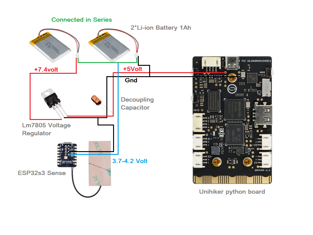


Comments