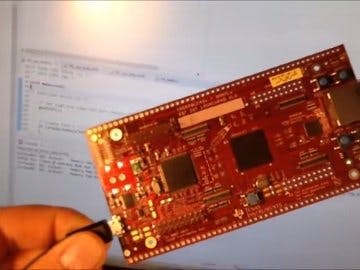
This article is a step by step tutorial for a freeRTOS project on the Hercules TMS570LC43x and RM57Lx LaunchPads.
Based on HALCoGen FreeRTOS examples (available from the help menu).
Configure the microcontroller in HALCoGenCreate new project File -> New -> Project
Select Device TMS570LC4357ZWT_FREERTOS or RM57L843ZWT_FREERTOS When naming the project, take care to use the same name later in CCS, and check that the location is your CCS working directory.
In the Driver Enable tab, select GIO GIO is going to drive the LEDs.
On the PINMUX - Pin Muxing tab, select GIOB (our user LED 1 and two reside on GIOB_6 and _7).
On the GIO - Port B tab, mark the pins 6 and 7 as output by checking the Dir box
All configuration is complete. Save the project and generate the code.
File -> Save Project File -> Generate Code
Write your Program in Code Composer Studio
Create new projectFile -> New -> CCS Project
Select TMS570LC43xx or RM57L8xx as target. Use the XDS110 debugger.
Check that the location is the same directory that was used in HALCoGen above. Choose Empty Project. HALCoGen has already created all source files we need.
Right click on your project, and select Properies
Add the HALCoGen generated include files to the project include path.
Set the Debug Flash options as documented on the url above.
Edit the HL_sys_link.cmd Add these lines:
/* USER CODE BEGIN (1) */
#if 0
/* USER CODE END */
// ...
/* USER CODE BEGIN (2) */
#endif
MEMORY
{
VECTORS (X)  : origin=0x00000000 length=0x00000020 vfill = 0xffffffff
KERNEL  (RX) : origin=0x00000020 length=0x00008000 vfill = 0xffffffff
FLASH0  (RX) : origin=0x00008020 length=0x001F7FE0 vfill = 0xffffffff
FLASH1  (RX) : origin=0x00200000 length=0x00200000 vfill = 0xffffffff
STACKS  (RW) : origin=0x08000000 length=0x00000800
KRAM    (RW) : origin=0x08000800 length=0x00000800
RAM     (RW) : origin=(0x08000800+0x00000800) length=(0x0007F800 - 0x00000800)
ECC_VEC (R)  : origin=0xf0400000 length=0x4 ECC={ input_range=VECTORS }
ECC_KERN (R) : origin=0xf0400000 + 0x4 length=0x1000 ECC={ input_range=KERNEL }
ECC_FLA0 (R) : origin=0xf0400000 + 0x4 + 0x1000 length=0x3EFFC ECC={ input_range=FLASH0 }
ECC_FLA1 (R) : origin=0xf0400000 + 0x4 + 0x1000 + 0x3EFFC length=0x40000 ECC={ input_range=FLASH1 }
/* USER CODE END */
// ...
/* USER CODE BEGIN (3) */
ECC
{
algo_name : address_mask = 0xfffffff8
hamming_mask = R4
parity_mask = 0x0c
mirroring = F021
}
/* USER CODE END
Add the Logic to the Main File
Edit the HL_sys_main.c file.
Add these lines:
/* USER CODE BEGIN (1) */
/* Include FreeRTOS scheduler files */
#include "FreeRTOS.h"
#include "os_task.h"
/* Include gio header file - types, definitions and function declarations for system driver */
#include "HL_gio.h"
/* Define Task Handles */
xTaskHandle xTask1Handle;
xTaskHandle xTask2Handle;
/* Task1 */
void vTask1(void *pvParameters)
{
   for(;;)
   {
       gioSetBit(gioPORTB, 6, gioGetBit(gioPORTB, 6) ^ 1);
       vTaskDelay(100);
   }
}
/* Task2 */
void vTask2(void *pvParameters)
{
   for(;;)
   {
       gioSetBit(gioPORTB, 7, gioGetBit(gioPORTB, 7) ^ 1);
       vTaskDelay(200);
   }
}
/* USER CODE END */
// ...
/* USER CODE BEGIN (3) */
   gioInit();
   /* Create Task 1 */
   if (xTaskCreate(vTask1,"Task1", configMINIMAL_STACK_SIZE, NULL, 1, &xTask1Handle) != pdTRUE)
   {
       /* Task could not be created */
       while(1);
   }
   /* Create Task 2 */
   if (xTaskCreate(vTask2,"Task2", configMINIMAL_STACK_SIZE, NULL, 1, &xTask2Handle) != pdTRUE)
   {
       /* Task could not be created */
       while(1);
   }
   /* Start Scheduler */
   vTaskStartScheduler();
   /* Run forever */
   while(1);
/* USER CODE END */
And that's it. You can now see the two LEDs flashing at a different speed, each controlled by an own FreeRTOS task.


Comments
Please log in or sign up to comment.