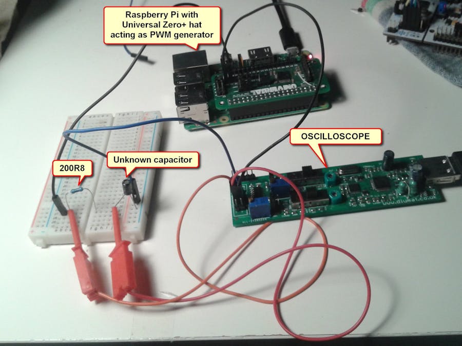
Quite often I need to find a proper capacitor for my project., I have a lots of them, but usually the markings are hard to read. There are many capacitance meters on the market, but if you do not have one you can your scope instead.
Some boring theory:When an uncharged capacitor is connected to a DC power supply through a resistor, the voltage across it increases exponential way until it reaches the voltage of the power source.
The voltage in in fuction of time and time in function of Vc is described by the formulas:
Actually the last will give us negative values of the time but will use the absolute value of it.
For easy calculation ln(1 - Vc/Vs) shouls be equal -1 and this condition is met when the Vc = 0.6324Vs
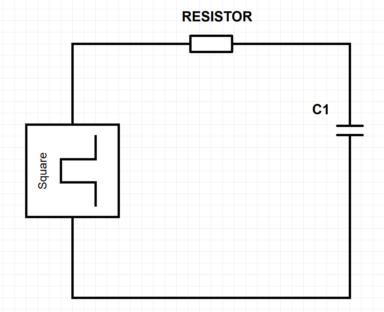
The test circuit:Instead of using the switch, we can use the source of the square signal instead.
As a square signal source you can use Arduino, function generator or something else. I use Raspberry Pi with the Universal Zero Plus hat because they are easy to program, I use them in my other projects and I already had one :)
In my setup the the unknown capacitor is in the range of uF. R = 200.8Ohm (measured with the multimeter). One of the oscilloscope channels is connected to the measured capacitor. The square wave source generates 100Hz signal. The frequency of the signal has to be low enough to see the whole voltage swing.
The Python script :
import spidev
from  UniversalZeroPlus import UZP

uzp0 = UZP(SPIspeed = 16000000)
ports0 = [uzp0.PWM19]
freq = 100
uzp0.SafeMode(1)
uzp0.PWMInit(ports0)
uzp0.PWMFrequencyDuty(ports0, frequency = freq, duty = 50)
uzp0.PWMStart(ports0)
My cheap ($25) oscilloscope software has a cursors which I
And using the formula: C = t / R
and the result is :
And the unknown capacitor is:
As you see this method is quite precise and quick. The whole measurement does not take more than 2-3 minutes (including the hardware setup).


Comments
Please log in or sign up to comment.