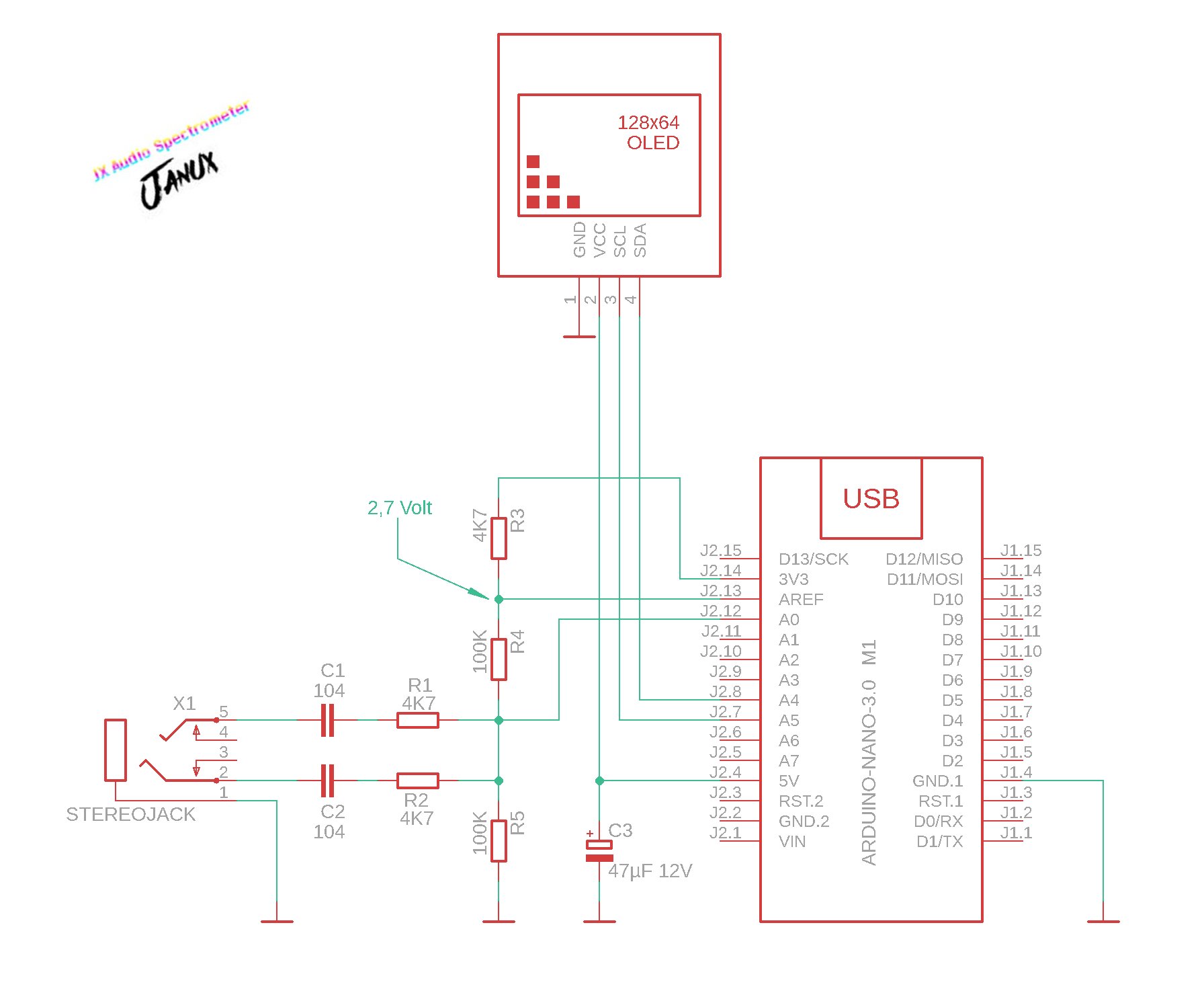
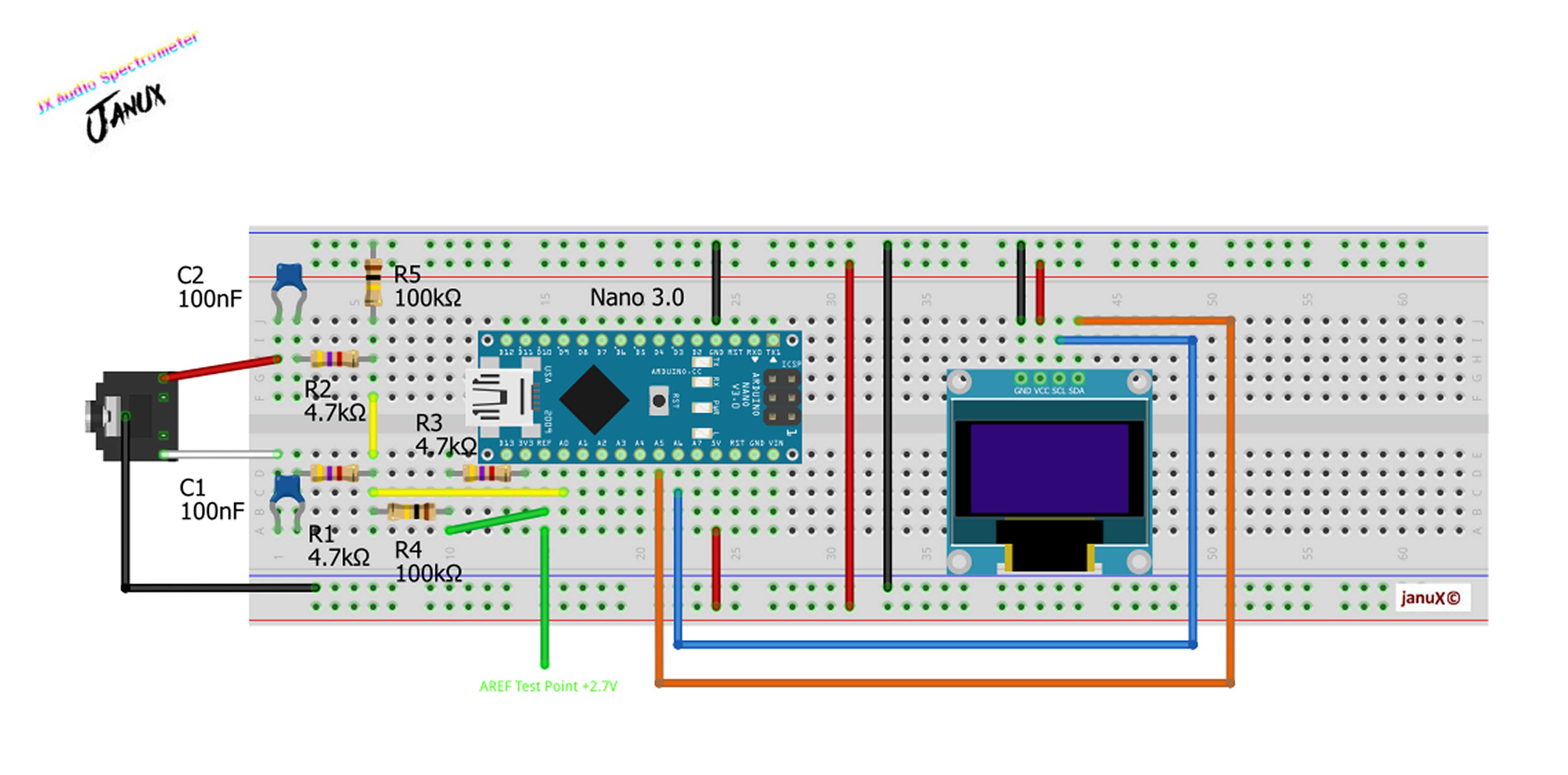
Using any Arduino model and the ArduinoFFT library, a 0.96 inch two-color OLED display, you can make this nice spectrometer, an interesting alternative to the classic VU Meter.
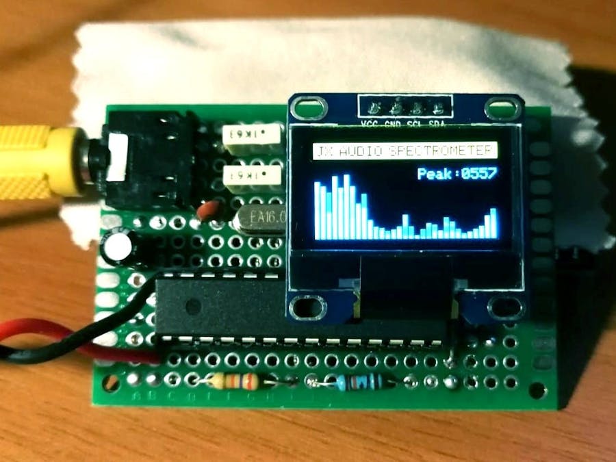
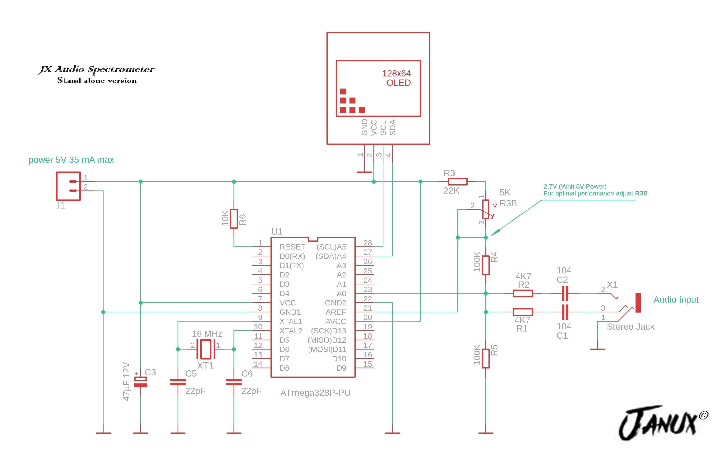
After trying it on a breadboard I made a stand alone prototype, burning an ATmega328 as clearly visible in the initial photo.
The problem is being able to fit the code into the Arduino memory, since most of the ram is occupied by the display frame buffer. In this regard, I suggest you use an I2C SH1106 display. I have not tried with the hardware but the SSD1306 model library only apparently takes up less memory at the time of compilation, but once the sketch has been executed this stops, just for the creation of the buffer at run time.
Be careful as there are identical displays on the market but with the VCC and GND pins reversed.
Observing the code you will notice that the cycle that draws the vertical bars starts from the value 2 instead of zero. This is not an oversight but I did this on purpose for the simple reason that the first two sampled frequency bands contain too much low frequency noise. Probably also because I connected it to the audio output of the PC and there is an impedance matching problem. Furthermore, strangely, the display I purchased has a horizontal resolution of 127 Pixel (from 0 to 126) instead of 128 as stated, if you try to write to column 127 this is plotted on the left side of the display, before column 0. It could be a problem caused by the SH1106 library which is basically a modified Adafruit_SSD1306 library.


Comments
Please log in or sign up to comment.