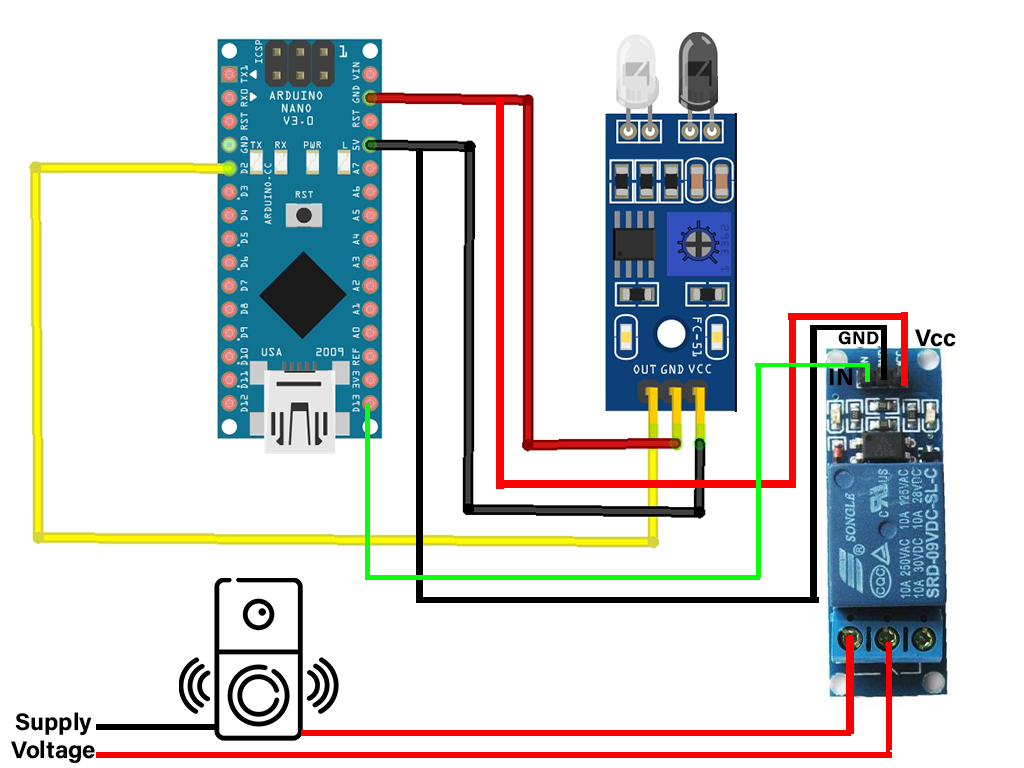
Making of this device is very easy and its cost is also very low around INR 450 ($5.95)
Maintaining Social distance is one of the best methods to escape from COVID-19. But we can't avoid some emergency visits to some homes. When we arrived at in front of a house, first we search the doorbell button/ calling bell button. And press the button. But in this situation, this doorbell button can also cause the virus to spread. When some infected person presses the button the virus stays on that button and after that when a non-infected person touches this button again the virus spread to him. We can avoid this dangerous situation by using the touchless doorbell. We can also convert a normal calling bell into an automatic bell by using a relay.
How does it work?When take our hand in front of IR Sensor, The sensor will send the signal to the Arduino board. And Arduino will power the buzzer. And eventually, the bell will ring.
In this article,
- Explain the working of IR Sensor Module.
- Interface the IR Sensor Module
- Control the relay module with Arduino Uno
- Explained each line of code.
Before starting we need to know about the IR Sensor module.
IR Sensor ModuleIR Sensor Module is an IR based proximity sensor. Mainly it consists of an IR LED, Photodiode, LM358 operational amplifier IC, Variable resistor.
Pinout
There are three pins in this sensor module.
Vcc - Power supply input (5V)
GND - Power supply ground
OUT - Output pin (Active HIGH)
WorkingThe IR LED transmitter transmits the light in the range of Infrared frequency. The wavelength of the IR wave is greater than the wavelength of visible length. The photodiode receiver will receive this transmitted IR light. It only conducts when a light fall on it. And it's reverse biased. And the current flow is directly proportional to the amount of light falling on it. Here the LM358 Operational amplifier (Op-amp) in voltage comparator mode. The comparator will compare the threshold voltage set using the variable resistor and the photodiode's series resistor voltage (PSR Voltage). Op-amp output is connected to the "OUTPUT" pin.
PSR Voltage drop > Threshold Voltage - Output is HIGH
PSR Voltage drop < Threshold Voltage - Output is LOW
The variable resistor is used to calibrate the distance at which the object should be detected.
Keypoint
When the object present in front of the sensor, the sensor output is HIGH, Otherwise it is LOW
This key point will help us in the programming part.
Thank You
I think all the information is given if you still think you need some more assistance the contact me v.jashwanth.2005@gmail.com


Comments
Please log in or sign up to comment.