


Hardware components | ||||||
 |
| × | 1 | |||
| × | 1 | ||||
Software apps and online services | ||||||
 |
| |||||
Hand tools and fabrication machines | ||||||
| ||||||
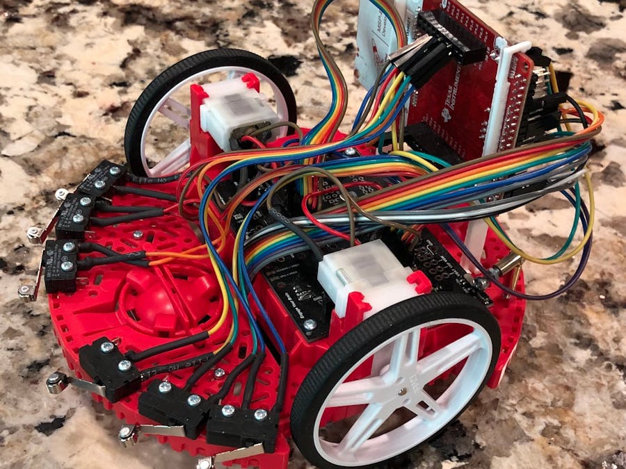
This tutorial provides a faster way to assemble the original TI-RSLK Basic Kit (www.ti.com/rslkclassic). Several tips are tricks are introduced, but the largest impact will come from 1. Using Quick Connect connectors and a crimping tool for the bump switches rather than soldering them (Quick Connect Female crimp connectors) and 2. Using the 3D printed stands to mount the LaunchPad vertically so that it's faster and easier to connect all of the jumper wires.
When you're not in a live workshop, the below time-lapse video is a great way to see what you'll be doing in this build, although please note that the bump switches are soldered instead of using the crimp connectors as mentioned above. Credit for this great time-lapse video goes to Arizona State University students Nicholas Carballo, Vineet Butala, Tony Tipton, and Jayanth Karthikeyan!
Tools you will need:- Electrical/painters/thick tape to hold down the headers for soldering, plus:
It's not needed when following the instructions in this Hackster post, but here's a link to the original Construction Guides from the TI-RSLK website: link
Set Your Soldering Iron temperature:- For leaded solder (preferred), begin by setting the soldering iron to 700F/370C
- For lead-free solder, begin by setting the soldering iron to 750F/400C
- If your soldering iron isn't working well (solder isn't sticking to the tip and it looks black or grey instead of "shiny" silver), the workshop leaders might have some of this great "tip activator" to help repair/restore your soldering iron tip.
In preparation, check out this great website to learn proper soldering techniques: https://github.com/maholli/lab64/tree/master/soldering
Instructions:This kit will give you a lot of soldering practice! =)
Assembly Duration: 3.5 - 6 hours, depending on soldering experience
Approximate time breakdown:
- Open packaging, gather supplies, prepare wires/tubing/headers = 30 min
- Solder headers onto LaunchPad = 20 min
- Cut traces and solder headers onto Motor Board = 90 min
- Solder wires onto motors = 20 min
- Solder headers onto Line Sensor = 30 min
- Crimp connectors onto wires and connect to bump switches = 45 min
- Attach motors onto chassis = 5 min
- Attach ball caster onto chassis = 5 min
- Attack tires/wheels = 15 min
- Attach bump switches onto chassis = 10 min
- Attach line sensor onto chassis = 10 min
- Attach LaunchPad 3d-printed stands = 5 min
- Connect wires to everything = 30 min
Step 1: Gather Your Supplies
Instructions: Open ALL packaging and set aside all components as shown in the picture below. Put any parts not being used back into the bags and/or box, (these extra parts are used in our free curriculum at www.ti.com/rslkclassic). Note: Keep your work space clean and organized so that you don't lose anything. =)
===========================================================
Step 2: Prepare Headers, Tubing, and Wires
Helpful hints to keep in mind for this step:
- To separate/cut the headers, use the cutting edge of your wire strippers or a pair of wire cutters. The "1x25" header is the header that's located in the line sensor packaging (pink plastic bag).
- If you don't cut the right amount of pins, that's OK and just use a combination, but do you best to follow the carpenter's adage "measure twice, cut once" =)
- There are also two 1x6 female headers not shown in the image below and they look a little different from all the other headers. They are for the motor board and will be used to connect the motors later on using the 3"+ long wires you'll cut next.
- For the two sets of 6 ribbon cable wires, peel away (fan out) at least 1" from the end of each wire (more than what the picture below shows).
- If you match the colors for both sets of wires, like shown below, it may make it easier to match wires and connect everything later on during the wiring steps.
- Follow instructions in this picture:
- Next, you will be using your wire strippers. Use the inner blade for cutting and the 22 AWG grooves for stripping, shown here:
- You will now cut off the black plastic end pieces on one side of the two sets of six wires and then (after the black end piece is gone), strip the wire by about a 1/4" as shown in the picture below. However, please note that in the picture below, they stripped way too much and there's way more than 1/4" of bare wire showing! If you do this, then just cut the extra bare wire down to get to 1/4".
- Using the scissor/blade section of your wire strippers, cut the 1x25 header into one 1x3 and three 1x2 pieces.
- Cut the 2 Male/Male end wires to at least 3" (not 1.5") and strip both ends. If you cut the wire right in the middle, it'll be about 4.5", which is good.
- Other than the changes above, follow the instructions in this picture:
===========================================================
Break time!? Before going on a break...1. Install the Energia IDE:Step 1: Go to shorturl.at/vyDX8 and click on the folder for your OS.
Step 2: Download everything in the folder and unzip files if needed.
Step 3: Click on the IDE installer to open and run. Accept default paths, file locations, and any popups required. Click the check box when asked:
If you downloaded the energia_driverpack from the Windows folder in the above steps, then double-click to open and run it. Click on Next and Finish buttons as needed.
3. Find the Energia program:Go to your computer's desktop, find the Energia folder, and double-click the Energia executable within.
===========================================================
Step 3: Solder LaunchPad Connections
Instructions: Take the 2x19 header that you previously made and insert it into the holes at the end of the MSP432P401R LaunchPad (see picture below). Insert it from the top with the longer portion of the pins facing upwards (not downwards!). Secure the header with tape, flip the board over, and solder all of the pins to the board.
*Caution: Be extremely careful to avoid burning your fingers! Don't touch a pin or be near a pin that is being soldered or has just been soldered, the heat passes right through the metal!
- Follow instructions in this picture:
===========================================================
STOP! Raise your hand and get your Soldering Job inspected before continuing
===========================================================
Step 4: Prepare the Motor Board
- Gather your Motor Board and the other materials shown in the picture below for soldering, including the 3 (not 5) 1x2 headers you previously cut.
- Note: When installing the headers, insert them from the top with the longer pins facing upwards (not downwards!). Secure the headers with tape, flip the board over, and solder all of the pins on the back of the board.
Notes on cutting the traces:
- Caution: The blade is very sharp! Ask the workshop presenter or an assistant for help you with these cuts.
- The traces that need cutting are the tiny slivers between the two square pads. All 3 of these tiny traces are circled (and/or pointed to) in the pictures below.
- Note: You will need to cut/scratch the tiny traces away using a few passes to make sure you cut deep enough, and then we'll check to make sure they're cut by using an ohmmeter to measure that the resistance is above 1kohm.
- It's OK to cut the black board underneath, it's made out of non-conductive fiberglass and epoxy, it's OK to cut it pretty deep, you won't hurt it. It'll look something like this:
- Follow the instructions in the picture below. The red lines point to the 3 traces that need to be cut, the yellow highlight is where you need to put the 2 female headers, and all the other highlights need male header pins:
- Below is what the finished Motor Board will look like, except that you won't have (and don't need) the header pins marked with a red X:
- Now use an Ohmmeter to make sure that the pads on either side of the 3 cut traces have at least 1kohm of resistance between them!
===========================================================
STOP! Raise your hand and get your Soldering Job inspected before continuing
===========================================================
Step 5: Connect Battery Terminals and Chassis
Instructions: Insert battery tabs as instructed in the picture and video below, inserting from the top rather than from within the battery compartment. Make sure the tabs are inserted as far as they can into the chassis battery compartment. Use pliers or standard screwdriver if needed.
Video showing how to insert the battery tabs from the top:
Place the board on top with the 4 battery tabs poking through and secure the board with the two 1/4" screws and nuts included in the bag with the black board. The nut will be placed in the battery compartment, on the other side of where you are inserting the screws. Solder the 4 battery tabs to the motor board, as highlighted in yellow in the picture below.
===========================================================
Step 6: Ready The Motors
- As a reminder from the preparation section above, the wires should be at least 3 inches long, not 1.5 inches as mentioned elsewhere.
- Twist the exposed copper strands to make it a more solid wire, then insert the bare wire into the soldering tab hole by a little over half way. Next, fold it over and twist it around the other half of the wire (the main portion of the wire that wasn't inserted through the hole) as shown in the picture below.
- Now solder the twisted wire and tab together, then slide the heat shrink tubing around the connection. This will provide electrical insulation and give the connection more strength since the tabs on the motor are a bit flimsy.
- Now use the heat gun to shrink the tubing. If you don't have a heat gun to shrink the heat shrink tubing, you can use the heat from the shaft of a soldering iron to make the tubing shrink.
Finished Motors, but they should be 3+" long wires (picture shows just 1.5" wires):
===========================================================
Step 7: Solder the Line Sensor Connections
**SUPER IMPORTANT** Make sure you match the picture below EXACTLY by soldering the header on the correct side of the board and with the pins facing the right way. Double and triple check before soldering!
Once you're sure it's right, solder the 1x11 header onto the Line Sensor board as shown in the pictures below. You'll be applying solder to the side of the board with all of the black chips, not the side with nothing on it (the side you see below).
Then, you need to flip the board over and add a solder bridge across the two holes labeled "3.3V BYPASS" highlighted in yellow in the picture below. Note: A solder bridge is just a big glob of solder used to connect the two pads. You can also solder on a small piece of metal from a wire or header. =)
===========================================================
STOP! Raise your hand and get your Soldering Job inspected before continuing
===========================================================
Break time!? Before going on break, download the Board file:- Open Energia
- Click on Tools -> Board: -> Boards Manager
- Click on Energia MSP432 EMT RED boards and click Install if needed.
- IMPORTANT: It's a massive file that needs to be downloaded, unzipped, and installed in the background. It's not unusual for it to take more than 20 mintues to complete everything!
============================================================
Step 8: Prepare the Bump Switches
IMPORTANT! IF you're in a TI-led workshop (or have the connectors mentioned at the top of this project), we will be using a crimping tool and crimp connectors instead of soldering the bump switches. The heat shrink tubing is optional, but recommended. If you're not in a TI-led workshop, just solder and heat-shrink the connections.
Preparation: You should have already prepared the long wires above in Section 1, Step 2. As mentioned then, the wires shown in the picture below are too long, they only need to be stripped enough that roughly 1/4" of bare wire is needed when crimping. Otherwise...follow these steps:
Next, you'll need to cut/prepare 12 crimping connectors like this:
Next, this is where we see if the 1/4" of stripping you did was enough. Using the next picture, size the length of the stripped wires so that the insulation fills the longer "flap" area at the edge of the connector, while the end of the bare wire roughly reaches the point where the connector flares from narrow to wide:
Instructions: It's hard to explain how to use the crimping tool in words, so I can show you in the class, but below is a short video demo that shows how we will be crimping the wires. **Get your first one inspected before doing all 12!**
Please ask for help from the instructor, assistants, or fellow students when doing your first one, and ask again if you get confused. Note: If you have time, here's an interesting website on the topic of crimping.
Once the connectors have been crimped onto the wires, push the open end of the connector onto the tabs of the bumper switches as shown in the pictures below...it usually takes quite a bit of force to push it on! =\
Connect the wires to the bump switches following the pattern in the next picture below. You'll notice that some bump switches have the hinge on the left and some have the hinge on the right.
The finished product will look like this, although we're using connectors instead of soldering and the heat shrink tubing isn't required.
===========================================================
Section 2: AssemblyStep 1: Gather Supplies
===========================================================
Step 2: Attach Motors
- Important! When inserting the motor clips (i) into the motor board (n), ensure that they are pushed all the way in so that the plastic "barbed clip" on the inside of it snaps into place on the top of the board locks it in place. At this point the bottom of the motor clip should be flush with the plastic chassis underneath (see image #4 below). If the plastic barbed clip doesn't lock fully into place, then it will be an obstacle as you try to insert the motor. You will then bend the plastic tab backwards and it will break!
===========================================================
Step 3: Attach Ball Caster
Note that the ball caster will get inserted on the more narrow end of the red plastic chassis.
===========================================================
Step 4: Attach the Tires and Wheels
Note: Getting the tire onto the wheel can be a challenge and can require significant finger strength, please ask the workshop presenter or assistant for help if needed.
===========================================================
Step 5: Attach Bump Switches
- IMPORTANT: Insert the screw from the underside of the red chassis, not from above as shown in the picture! It's much easier to screw the nut onto the topside rather than from underneath!
- Also, make sure you have the 6 bump switch levers/hinges pointed in the right direction (picture #1 below) before attaching the nut.
===========================================================
Step 6: Attach Line Sensor
Before attaching the line sensor, attach the wires to the header pins on the line sensor and run the wires through the gap in the plastic chassis as shown in picture #3 below. To make sure you did it right, notice that the 8 sensors on the board (black chips) can still be seen after installation, and the header and wires are run through the gap by the battery compartment.
Again, make sure that the pins of the line sensor board are pointed in the correct way...as shown in picture #3 below. This will allow you to feed the wires through the small slot and connect them up properly.
===========================================================
Step 7: Attach 3D Printed LaunchPad Stands...or the standoffs included in your kit
- If you have the 3D printed stands from Tinkercad, install them as shown in the picture below and put the LaunchPad in as shown.
- Put the bottom in first, then slightly bend the tops of the stands backwards so you can put the LaunchPad into the top groove, and allow the tops to bend back over to the front to secure it.
- These stands make it much easier to wire and re-wire everything. Note where on the LaunchPad these stands are located so they don't interfere with headers or components.
- IF you don't have the 3D printed stands and need to use the standoffs, please note that the screws for the LaunchPad Standoffs do not fully screw into the LaunchPad, they are loose and that's OK. Don't apply extra force or you will break them.
- Only follow this pic if you DON'T have the 3D printed stands:
===========================================================
Section 3: WiringStep 1: Motors
- Remember that your wires should be at least 3" in length to make it easier to make these connections without putting a strain on the fragile motor tabs that you soldered the wires to.
- Note that the female header that you will be plugging into is a little bit underneath the motor assembly.
- Follow the instructions in this picture:
===========================================================
Step 2: Bump Switches
- Note: We used crimped connectors here to connect to the bump switch tabs instead of soldering directly to the bump switches.
- IMPORTANT: In the next step, you will be inserting the wires into the BACK of the LaunchPad using the Male end of the wires, not on the front side of the LaunchPad as shown in this picture.
- Instruction: Connect wires as shown in this picture:
===========================================================
Step 3: Motor Board Logic
- IMPORTANT: In the next step, you will be inserting the wires into the BACK of the LaunchPad using the Male end of the wires, not on the front side of the LaunchPad as shown in this picture.
- Other than the note above, follow the instructions in this picture:
===========================================================
Step 4: Motor Board Power
- Follow instructions in this picture:
===========================================================
Step 5: LaunchPad Power
- Follow the instructions in this picture to connect power:
===========================================================
Step 6: Line Following Sensor
- Note: The wires for the next step are barely long enough, so make the path for the wires as straight as possible.
- Follow the instructions in this picture:
===========================================================
Step 7: Attach LaunchPad
- Skip this if you're in a TI-hosted workshop and already installed the 3D printed stands available on Tinkercad (during Section 2, Step 7 above).
- If you don't have the 3D printed stands, then attach the LaunchPad to the standoffs as follows:
===========================================================
***CONGRATULATIONS! YOUR TI-RSLK IS BUILT!***Now, let's see if your robot has been wired correctly... =)
===========================================================
With no batteries installed, connect a MicroUSB cable (included in the MSP432 LaunchPad box) between your computer and the TI-RSLK.
Using the Google Chrome browser, go to http://dev.ti.com and click on the window that appears on the left hand side to install the TI CLOUD AGENT, then refresh the web page.
- If you don't already see the text "ID: MSP-EXP432P401R" as shown below, follow the instructions in the box to install the TI CLOUD AGENT.
Next, click on this link and follow the prompts as directed to download the required plug-ins.
When complete (you may have to refresh your browser), focus on the progress bar at the very bottom of your browser window. You should see the browser make contact with your MSP432 LaunchPad and load the program.
Once the status bar at bottom has finished loading the program into your LaunchPad, test your robot as follows:
- Push in each of the 6 Bump Sensor switches at the front of the TI-RSLK to see if each red light changes to black.
- Pass your finger along each of 8 Light Bar sensor elements under the TI-RSLK to see if each red light changes to black.
- Moving the dot on each of the numbered slides to the right to make sure the motors spin in the correct direction.
Common issue: Did your motor spin the wrong direction?? If so, then the wires for that motor are plugged into the wrong holes, so simply swap the wires into the opposite holes so that the motor will go in the other/right direction. See 2nd picture below:
If there is a problem, check all of your wiring and make sure it's all wired correctly.
===========================================================
What's next? A program! Time for some code...Use the Energia files in the Attachment Section of this Hackster post to run two simple applications, named Demo #1 and Demo #2 below.
FIRST, check to see if you need to download the Board File in Energia: In Energia, go to TOOLS->BOARD->BOARDS MANAGER and install the one labelled "REDLaunchPad w/ msp432 EMT (48MHz)", which is the LaunchPad microcontroller board that's used on the TI-RSLK.
NEXT, click on Tools->Board to verify that you have the right board selected: “REDLaunchPad w/ msp432 EMT (48MHz)”
THEN, select the right serial port. Click on Tools->Port-> (Windows = Pick one that starts with COM, it's usually the lowest number listed) (Mac = Pick one that says usbmodem or usbserial) (Linux = Pick one that says ttyUSB or ttyACM)
Demo#1 uses the bump switches to detect when you bump into a wall and re-direct the robot (aka "Wall-Pong"), here's how to get it running:
- Go to the attachments section of this hackster post and download the WallPong demo program file called "rslk_bump_switch_demo_wallpong_code.ino"
- Navigate to your MyDocuments->Energia folder and create a new folder with exactly the same file name "rslk_bump_switch_demo_wallpong_code", then paste the download .ino file into this folder.
- Open Energia, click on File->Open...
- Browse to the location of this .ino file and select it.
- To re-open this in the future, all you now have to do is select File->Sketchbook->RSLK_bump_switch_demo_WallPong
Last, click Sketch->Upload to load this program into the robot.
IMPORTANT Note: It’ll start moving right away! You’ll see what happens when you touch a bump switch. Depending on which bump switch it is, it'll reverse and change directly from a slight amount to a very large amount.
- If you'd like to test it on the floor, then unplug the robot from USB and install 6 AA batteries so that it can run on battery power.
Note: You will need walls of some kind to bump into or it'll just keep going straight.
Demo#2 is some basic starter code for experimenting with and using the line following light bar sensor to follow a wide black line (roughly 3/4" wide), such as black electrical tape on a white floor or a permanent marker used on white paper.
- You follow the same routine as used for Demo #1, but the file and folder has a different name of course. =)
- When you're ready for it to move, the robot won't start moving until you press SW2 on the side of the LaunchPad.
- IMPORTANT: You'll need to use (un-comment) one of the sections that's commented out to determine the right timing delay for your specific line sensor's sensitivity to light, your lighting conditions, and your type of black/white line contrast in your setup.
- Unplug the robot from USB and install the batteries to let it run by itself on the floor.
===============================
...and more next steps... (***coming soon***)Resources:Energia drivers for MSP432 LaunchPad with instructions: link
This pinmap of the MSP432 will be helpful: http://www.energia.nu/pinmaps/msp-exp432p401r/
RSLK Energia Library: https://github.com/fcooper/Robot-Library
How to create your own Energia Library(or port one from Arduino): link
Technical Reference Manual MSP432P401R: http://www.ti.com/lit/pdf/slau356
Datasheet MSP432P401R: http://www.ti.com/lit/gpn/msp432p401r
CMSIS files that are included in CCS when MSP432support is installed on the initial CCS setup:C:/ti/ccsv8/ccs_base/arm/include/CMSIS
MSP432 Register-level Examples: http://dev.ti.com/tirex/#/DevTool/MSP432P401R%20LaunchPad%20-%20Red%202.x%20(Red)/?link=Software%2FSimpleLink%20MSP432P4%20SDK%2FExamples%2FDevelopment%20Tools%2FMSP432P401R%20LaunchPad%20-%20Red%202.x%20(Red)%2FRegister%20Level


Comments