This is my very first project uploaded here, also it's my very first article originally written in English (I'm a Spanish spoken). So, sorry for my English.The idea
The principal idea of this project is made a device that registers the energy consumption (i.e. of a house) during a certain period of time.
Of course that idea is not new, in fact, there are various projects about that, in particular, one very well developed and documented is Open Energy Monitor.
My project is principally based on Open Energy Monitor's Arduino library EmonLib.
The basis of the projectThere were some features of the device that could not be missed.
- Keep the time even in a lack of power (battery back up RTC).
- Store all collected data in a non-volatile way (SD card).
- An easy way to sense electrical parameters of a relatively big installation, i.e. a whole house (current transformer and ac/ac transformer).
The general idea is a device that connected to an installation can measure every -let's say- ten seconds, voltage and current, and calculate active power, power factor, energy, etc. Then, every i.e. five minutes save these parameters to SD card (in a.CVS format), with a timestamp. This recorded data allow us a later analysis in a computer.
A possible upgrade of this project is to add an LCD display to show all electrical parameters in real time. Additionally, implement a configuration menu (instead of a serial connection for configuration).
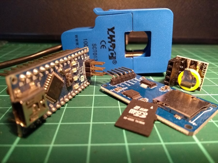
The hardwareThe circuit is based in an Arduino Nano, but, it could be constructed arround an Arduino Uno or any compatible board, even with and Atmega328 and few components.
The principals peripherals are a DS3231 RTC module and an SD card reader.
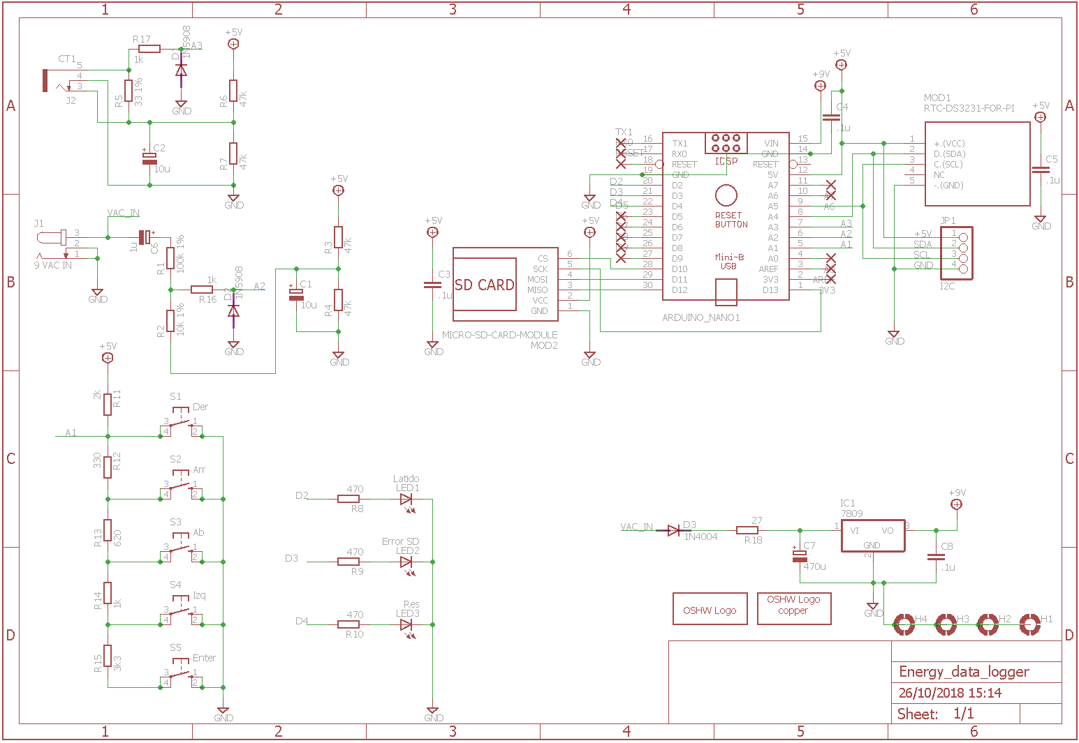
- The DS3231 is connected to the processor via I2C bus (SDA -> A4 and SCL -> A5 pins in Arduino, plus power).
- The SD card module interface with Arduino over SPI connection (MOSI -> D11; MISO -> D12; CLK -> D13; CS (SS) -> D10).
In order to measure high-level electrical parameters, we need to "transform" that signals into an Arduino compatible voltage level (0 - 5Vdc).
First, we need to understand how AC power works, and how appliances interact with the electrical system. This is very well explained here in Open Energy Monitor web. And here the explanation about the maths involved.
Now we know that we have to measure two parameters: voltage and current. And later calculate all the others parameters.
Current measurement:
For current measurement we use a current transformer (we use the YHDC SCT 013-000), it allows us to get a relatively low voltage, proportional to the current we want to measure without cutting the mains cables.
Then we need to interface the "CT" with our Arduino, that only allow 0-5 Vdc in its analog inputs. We use the following circuit:
A complete explanation of the circuit and how to calculate the values can be found here.
Voltage measurement:
We use an AC-AC transformer to reduce de AC mains voltage, to 9 Vac (could be other voltage similar, like 6 or 10 Vac) additionally the transformer provides galvanic insulation.
To interface that voltage with an Arduino analog input we use a circuit similar to the current sensing one with a few variations.
Here we can view the complete explanation.
Both in the voltage and current circuits, a series resistor and a TVS diode have been added to the analogs inputs for protection purposes.
Finally, we add a few components for feedback:
Two LEDs (with a 470 ohm resistor to GND):
- "Heartbeat" LED - Blink while the program is running. Attached to digital pin 2.
- "ErrorSD" LED - On when an error in SD card occurs (not connected or read/write error). Attached to digital pin 3.
Some pins were reserved for future upgrade:
- Digital pin 4, for an extra LED.
- Analog pin A3, for an analog keyboard.
Basically, the sketch does three things:
- Keep the time.
- Read electrical parameters.
- Stores that parameters in an SD card.
In the setup section, all pins are initialized, also the SD card. An instance of emonlib is created and a current an voltage measures are set. The RTC is initialized and a function for setting the time (over the serial monitor) is called.
In the loop section, periodically the electrical parameters are read, these measures are based in features of Open Energy Monitor's Arduino library EmonLib.
Then, that parameters are formatted in a human readable form, a time-stamp is added and are transmitted over serial port.
Every certain period of time, the formatted info is stored in an SD card, in a.CVS file, in a new line each set of measures.
All these operations are separated into functions for a better understand and maintenance of the software.
CalibrationMaking the long story short, follow the next steps:
Start whit this:
- Measure Vac mains voltage.
- Measure Vac voltage at ADC input pin.
- Voltage calibration constant = Vac main / Vac ADC
- Replace the calculated constant in the following line:
emon1.voltage(pinTension, 234.26, 1.7); // Voltage: input pin, calibration, phase_shift
- The theoretical value for current constant, according to the burden resistor used (33ohm) is: 60.6.
emon1.current(pinCorriente, 60.6); // Current: input pin, calibration.
For a more precise calibration continue with this steps:
- Connect the Energy Data Logger on a resistive load around 2000W (i.e. iron, electric heater, etc.)
- Measure Vac at the input of the device.
- Measure the current consumption of the device.
- Check these measures whit the values reported by the energy data logger (thru serial monitor).
- Change the constant values (voltage, current, phase_shift) to adjust the outputs to be equal to the measures and the real power equal to apparent power.
- Reload the sketch.
- Repeat.
If you want to read a detailed explanation of calibration theory an procedure read in Open Energy Monitor web, here and here.
ConclusionsIt works!
This gadget provides a simple and cheap way to monitor and analyze our energy consumption.
But the real joy was design (mostly copied) and construct it and, why not, write this article.
I'm waiting for yours comments.
Remember that it is a work in progress, the PCB final version has not been tested yet, it may have some errors, be careful.


_1x_bGT19vVAby.png?auto=compress%2Cformat&w=40&h=40&fit=fillmax&bg=fff&dpr=2)


Comments
Please log in or sign up to comment.