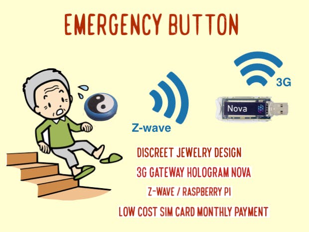
One of the main problems for elderly people is keeping their balance while walking. It is getting more and more difficult to move, and if they fall down it's very complicated to get back up. My family is calling my 98 years old grandmother every evening to check for this kind of problem. There are some emergency buttons that can help, but you often have an expensive monthly payment for the call center. In addition, most old age people don't like to wear some gray plastic technologies around their neck. So my question is : How can you make a cheap, reliable device which is easy to integrate but which is also discreet and which would cost them a minimum monthly payment?
I built a lot of IOT devices at home and for work, most gateways are using the Wifi internet box or the smartphone connectivity... But what if someone doesn't have any of those two? It is still very commun for age people !
Hologram NOVA is a perfect way to answer this question. It give a inexpensive way to upload the few necessary sensors datas. We can then choose how we receive the informations (mails, notifications, messages...). Moreover, information transfer is really fast so we can use it in time dependent application like an Emergency Button !
For the embedded part, I choose to use Z-wave. It is a great protocol for home automation so it will accelerate the development.
But Z-wave don't offer much affordable development board. At the beginning, I was hesitating to dismantle a NodOn button. Then I discovered Z-Uno, a programable Z-wave protocol using Arduino IDE. Perfect to build a small low energy device !
Welcome to the build tutorial. You should find here all the informations you need to make, modify or adapt it at home. The code, 3D design and pictures are available on a GIT.
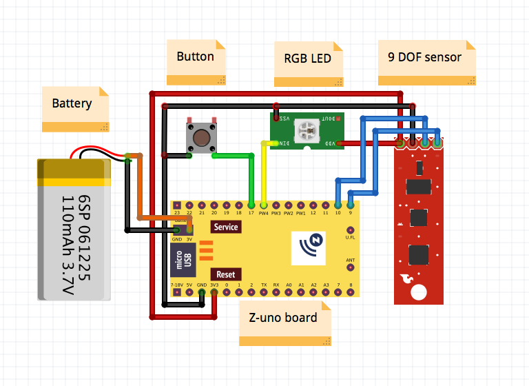
The first idea of the project is to build an emergency button. If I have time, I will also add a 9 DOF sensor to also detect if a person fall. This second part can be very tricky, even commercial products have trouble doing it... But it's interesting to open a bit more the project with more sensors ;)
Step 1 : Button Hardware and autonomyThis part is pretty simple. I didn't add a circuit to charge battery, it will depend on the autonomy of the system.
The Z-uno board has some very interesting documentation. Here we can understand a lot about the powering options on page 30. And Here we have the actual characteristics of the different mode.
An important thing to notice : if we want to have some interresting durability on a small battery, we need to remove the R12 resistor (which is not really one, it's 0 ohm!).
With this condition, we can use FLiRS mode and have 70uA. BUT WE CAN T USE THE USB ANY MORE! See the forum here for more information.
With 70uA on a 200mA batterie, we should be able to have 4 months autonomy (a bit less with the other components of course...).
It's not to bad, but I will also check a combine sleep mode to be more efficient...
Step 2 : Nova 3G gatewayI saw a lot of advertising about Hologram Nova on the DIY community recently, so I decided to buy one. The device arrived very quickly and was easy to configure. Now let's try to link the API !
There is some very good tutorial to setup the environment. In here you have all the necessary informations to install the Hologram repository on a Raspberry Pi.
Once it's done, we can easily send some messages using Python. On the GIT repository of Hologram, we have some examples to send simple text messages.
We can also send datas to the webserver with simple command line. Here is my first "This is a Z-wave Emergency" on 3G !
Here is the online page. I just received my three test messages :
And if you want to track me, here is my latitude and longitude. It 's pretty accurate!
Now we have the Nova environment running, let's install OZW. The repo is here.
The USB dongle from Aeotec has an embedded batterie. We can include devices on the network by just pressing the button when the USB isn't plugged.
Once OZW is installed and the Z-uno is paired with the stick, let's install OZW Control Panel from here to see if everything is working.
Write your dongle port PATH on device name and don't check USB box. It's not working.
Here we can see the USB aeotec dongle controller is recognized as node 1 and my Z-uno as node 2. Use add or remove device if the inclusion didn't work well. I also added a fibaro power switch as node 5.
Now the network is created, we need to install python-openzwave from the same repo :
"cd python-openzwave" then "sudo make install"
It takes a while on the Raspberry Pi. Once it's done, check your USB port with
'ls /dev/tty*"
You should have a ttyUSB0 if your are using a Aeotec Gen 2 like me. But other dongle can be ttyACM0.
Step 4 : Link Nova and Z-waveNow, we have our two dongles working, we need to create a little program to link everything together
first copy the example sniffer program : "sudo cp examples/api_sniff examples/Gateway_Emergency_Nova-3G_Zwave.py"
And then "sudo nano examples/Gateway_Emergency_Nova-3G_Zwave.py" to modify it.
You are now in the nano editor of the python file. First modify if necessary the line "device="/dev/ttyUSB0" for your port. Then on "config_path" check if it's the right one. For me it was "../openzwave/config" and I had to modify it as "../open-zwave/config"
We also need to add "import subprocess" at the beginning
Last thing, we trigger the hologram command when the zwave button is pressed :
def louie_value_update(network, node,value):
print('Louie signal : Value update : {}.'.format(value))
print('Sending Emergency message on NOVA-3G')
print subprocess.check_output(['sudo','hologram','send',"ALERT!! Zwave Emergency Button ON"])
Now, ctrl X then Y and enter to save.
We start the program with "python examples/Gateway_Emergency_Nova-3G_Zwave.py"
Then press the Zwave button and you should receive your emergency message !
And of course the result :
Once you received your Z-UNO board, you can go to this website to start programming it. It works very good on my Mac, just be carrefull of two things :
- I tried at first with the version 1.6.9 and it didn't work... Just download and install the old 1.6.5 version before starting!
- When you press "Burn Bootloader" don't forget to select the "programmer" "Z-UNO programmer".
Then everything worked great. You have several exemples on "Files" "Exemples" "Z-uno". Which will simplify a lot the software development for this board.
Step 6 : 3D designOn the first version of this project, I was using an ESP8266 wifi board. It was a bit smaller, so I had to adapt my design.
Here is the new version made with Sketchup. The render don't look as good as SolidWorks, but the 3D printed result should be more or less the same :)
If you are interested in designing in Sketchup with a Z-UNO board, I just made an "approximate" design. It's available on the GIT (File 3D_design/Z-UNO_design.skp). I didn't add the antenna, it's a bit annoying to set it on the exact position I need ^^
Here on the left is the the first emergency button design based on Solidworks with an ESP8266 chip. The Render looks great, too bad I don't have a licence any more... On the right is a little test of fusion 360 software. It looks really beautiful too, but I didn't had time to finish it.
Here are all the parts, now it's time to assemble everything together!
The electronic was a bit messy on this first assembly :
- I have only one Z-Uno to build my two projects (I also made a Magic Frame / Zwave project). So a part of the wires are not necessary like the UART and the external power supply...
- The second reason is a little problem with the WS2812 LED. I don't know why I have to put two in series and then, the second one take the number 0. It can be a library problem, or maybe my electronic is a bit weak to control the LED directly (but throw one LED it works). A bit more work to do!
- There is no part holding the enclosure top and bottom together. I need to improve this on the next version !
The bracelet is printed as one single element. This design is flexible enough to put it your wrist and still seems very solid (done many test, still not broken!). The best is to adapt it to the wrist of the person (mine are very small).
And here is the final result, with all the electronic inside (including a 200mA battery). Under the black circle is the button and under the white circle the RGB LED. When you press the black button, the device send an emergency signal and start blinking red.
I hope you enjoyed reading this tutorial. I was a bit short on time at the end of the project as it was a bit long to get all the necessary devices to have everything working together.
I really liked playing with Z-wave and Nova. I will continue to improve this tutorial, so I hope to see you soon !


_3u05Tpwasz.png?auto=compress%2Cformat&w=40&h=40&fit=fillmax&bg=fff&dpr=2)
Comments
Please log in or sign up to comment.