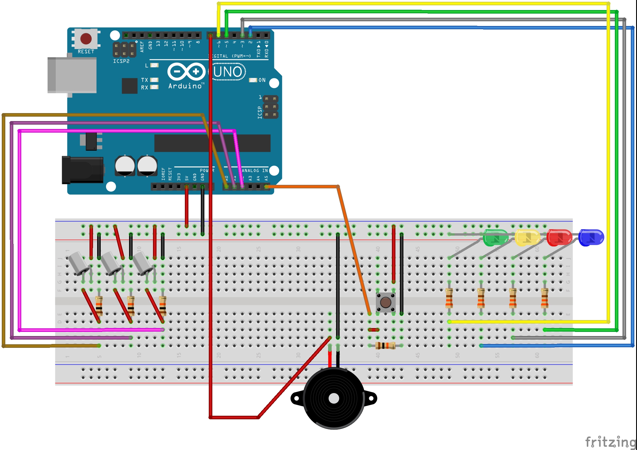
I am always paranoid that the sump pump in my basement will fail resulting in a flood. I also like to tinker and was looking for a practical project to experiment with an Arduino. This project is where my two objectives intersected.
Project Specification1) Multi-stage detection: I wanted to be able to detect when the pump cycled, when the water level was above normal elevation (early stage failure), and when the water level was close to over topping the sump pit (critical failure) .
2) Visual status indicator
3) Distinctive audible status indicator
4) Test/silence button
5) Easily connect/disconnect the sensor stack from the Arduino
6) Future expansion to a network connected version
Sensor SelectionI considered several options for sensing the water level; ultrasonic distance sensor, floats, liquid sensors of various types, etc. Ultimately I decided to keep it simple and use a set of 3 vertical float sensors as they are inexpensive and should have a longer service life than several of the other types under consideration.
The sensors are mounted to a piece of threaded stainless steel rod with segments of 1" wide bar aluminum. Mounting the sensors to threaded rod made it very easy to set the sensors to the appropriate elevations. The rod hangs from the top lip of the sump pit via an 'L' shaped segment of bar aluminum.
Status IndicationI chose to use a series of 3 LEDs (Green, Yellow, Red) to represent the water level in the sump pit. Under normal operating condition the green LED will burn steady when the pit is empty and will blink once the water level comes up a bit. A yellow LED will light in addition to the green LED and a piezo alarm sounds if the water level exceeds the normal maximum water level. Finally, a red LED will light and the piezo will continue to sound when the water level in the sump pit is close to the top, but hasn't yet started flooding my basement.
A push button is included to silence the alarm if desired. When the water is at a normal level, the button tests that the piezo is working properly.
Finally, I included a fourth LED in my design. For this version the LED is not used and can be omitted. I intend to use the LED as a network connection indicator in a future iteration of the project.
I wanted a distinctive alarm tone. I know it will be 3:00 am the first time it detects an imminent flood and it's nice to know implicitly that the alarm isn't a fire. To ensure I could separate the sump pump alarm from the smoke detectors, the code implements a Morris code routine. I have mine set up for S.O.S. but you can set the pattern for anything you like. The instructions are in the code comments.
The piezo I used for this project was re-purposed from an expired smoke detector. It is very loud and works great. To determine the frequency where the piezo was loudest, I simply wrote a sketch to step up through the frequency range while also outputting the frequency to the serial console. I set the frequency in the final sketch to match the loudest frequency for my specific piezo (3200hz). I recommend you determine the loudest frequency for your specific piezo should you choose to build this project.
As I knew I wanted to modify and grow this design at some point in the future, I wanted an easy way to disconnect the sensor stack from the Arduino. As I already had a bunch of RJ45 keystone jacks and Ethernet cable laying around, I just used that. As the floats are basically on/off switches there are no special considerations for the connection as RF interference is not a concern.
Physical ImplementationI soldered all the components to a prototyping board to create a custom hat for the Arduino. Note that I only had 2 colors of LED on hand the day I built it, so my implementation is less colorful than I had intended. The Arduino was then mounted to a piece of hard board and the piezo and Ethernet jack were attached with hot glue. As I had a section of metal electrical conduit on the wall next to the sump pit, I attached a magnet to the back (re-purposed from a dead hard drive) to hold it up in an easily visible position.
The sensor stack is easily constructed with threaded rod, aluminum bar stock, some nuts and lock washers. I cut 3 pieces of aluminum bar stock to about 2", drilled 2 holes in each, one end holds the sensor, the other holds the rod. Then I attached an 'L' shaped piece of bar stock to allow the sensor assembly to hang from the lip of the sump pit. The 'L' shaped piece is just aluminum bar stock bent to 90 degrees. Once the 'L' shaped hanger was in place, I set the sensors to the appropriate elevations and tightened up the nuts.
The pins on the Arduino were choose specifically to allow the addition of an Ethernet shield at a later date. Network connectivity would allow digital notifications to be sent (email, text messages, etc)
The lowest sensor could be utilized to count the number of times the pump cycles and the volume of water pumped could be calculated.
Final ThoughtsThis was a fun introduction to Arduino programming and I hope someone else out there finds a bit of inspiration from my project.


_ztBMuBhMHo.jpg?auto=compress%2Cformat&w=48&h=48&fit=fill&bg=ffffff)


Comments