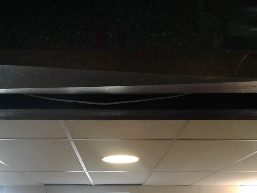
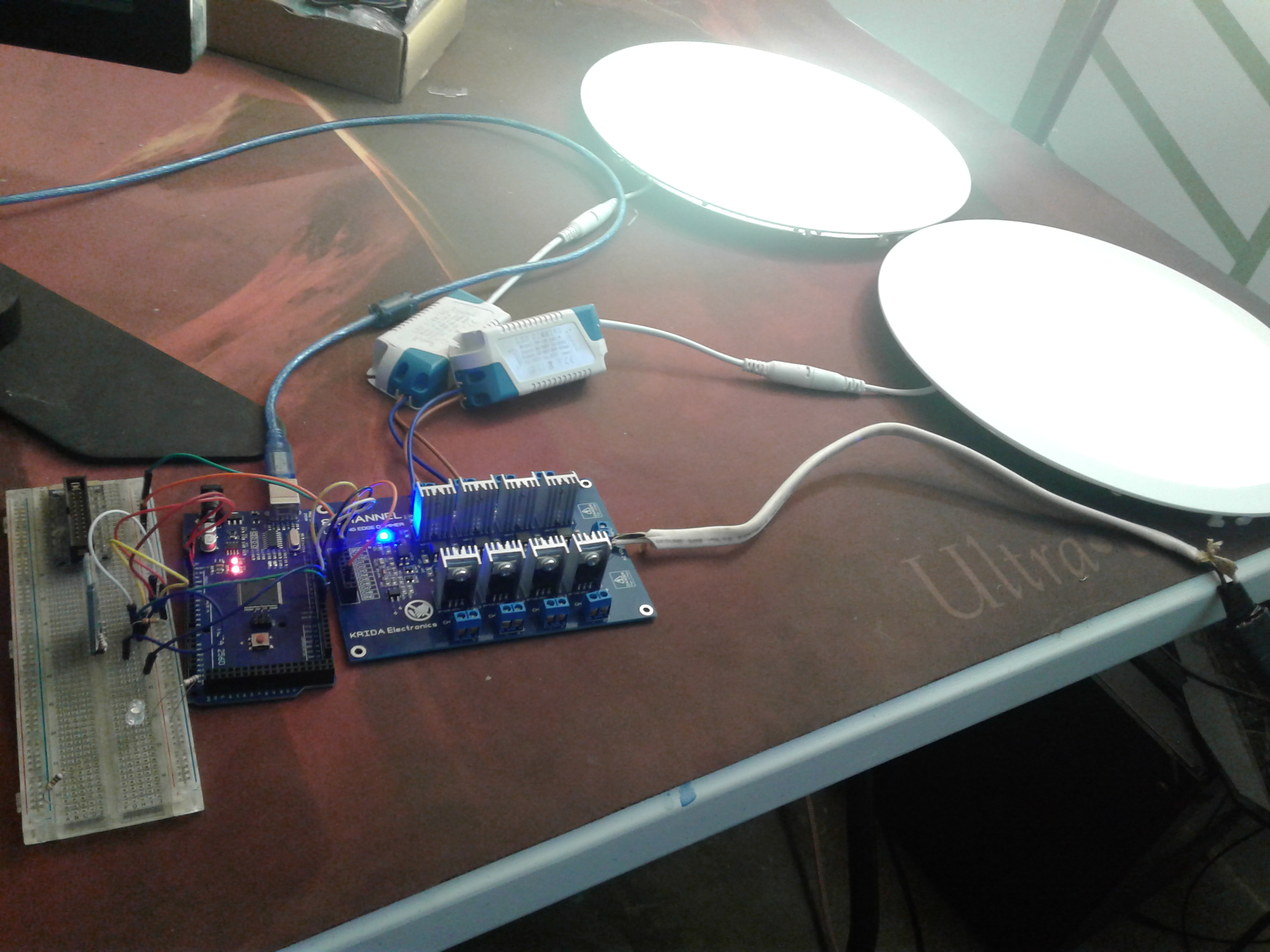
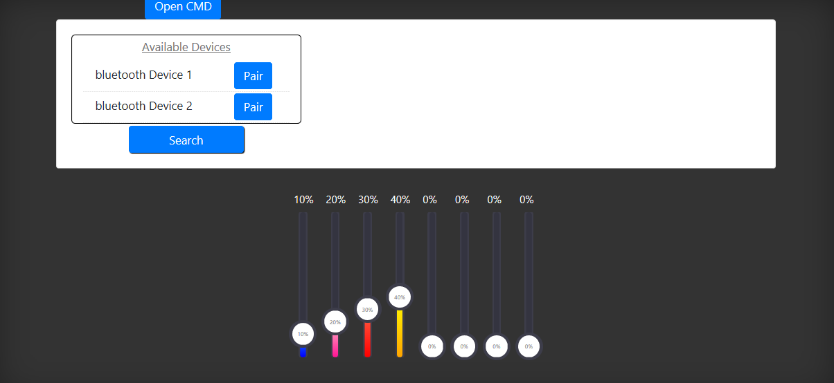
I have 8 dimmable LED lights in my ceiling I have installed. I currently have them hooked up to an AC dimmable module. This is hooked into an Arduino Uno. I can control the brightness of all of the LED lights by the Arduino. The Arduino has a Bluetooth module hooked up into it which allows me to control the lights by the phone. My plan is to remove the AC dimmable module and replace it with a 8 channel AC dimmable module so I can control each light independently. I will also remove the switch from the room and replace it with a touchscreen that is hooked into the Arduino. I will also have to create a DC power supply as the main AC line will go through the Arduino and the dimmable board. I plan on writing the software to control the lights from the phone and any device in my home that has Bluetooth. When everything is tested and good, a raspberry pi will come into play as a mini server that will host a site that I can access in home by the router and an IP. Anything in my home will be able to be controlled by connecting an a relay or dimmable AC module to it and Bluetooth through Arduino.
-----------------------------Update 6/23/2018
The 8 channel AC dimmer module has been implemented into the project and Arduino code has been written to make the module work. There was no working code for this module online so it took a full day to get this to work with multiple TRIAC'S. Next step is to design a PCB that will act as a central unit for all components to hook into, including having a PSU on the board to drive the Arduino. This unit will sit inside the wall, so it will take 110 AC voltage straight in.
I have drawn the conclusion that a large touchscreen will be easiest to implement with the Raspberry Pi. I have ordered a Raspberry Pi 7" touchscreen that will act as a central unit to change the values on the dimmers. Eventually a server will be setup and host a website that will be ran that controls all the units in my house including this light project. This will be the next step after the dimmer system is complete.
Also to note, I will be designing enclosures in Autodesk Fusion360 and 3D printing them on my 3D printers. This should help make sure that short circuits don't occur or fire hazards. Insulation and other items are in my ceiling. I want to avoid any occurrences of anything touching the PCBs, short circuiting, and creating fires.
-----------------------------Update 7/3/2018
I have a raspberry pi 3 working with an element14 7" touchscreen. I am currently working on the server and client side UI that will display on the screen. This has been a battle as I have had to learn nodejs. The real problem was getting this project to work on windows in visual studio. I could not get some libraries to load through NPM in visual studio. After 2 days of battling it, I gave up so I would not waste any more time on it. I am writing all my code in Visual studio and then transferring it over to the raspi to see what the UI looks like. This is time consuming but gets me closer to the project goals. Once I have the server/ui finalized, I will be able to hop back on the electronics side. I have my pcb's that I designed ready to be tested. Hopefully I have no roadblocks with it and I can skim through the electronics side straight to the 3d design and printing of enclosures. I will keep you all updated as I move along.


Comments