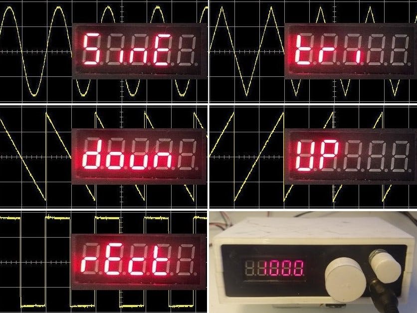
The ATtiny1614 is part of the new breed of ATtiny microprocessors. One of its features is a built-in Digital-to-Analog Convertor or DAC. This project started out as an experiment in finding what the limitations were in generating sine waves using the internal DAC.
The concept is simple, fill up a table of voltage levels for various points on a sine wave and repeatedly play them back via the DAC.
Consider storing 256 points for one complete cycle of a waveform. To output this waveform at 1Hz, you need to output the 256 points in one second. So the clock speed necessary to do this is 256Hz. At 10Hz, clock speed needs to be 2560Hz and at 10kHz clock speed needs to be 2.56MHz. Note this means the "loop" that outputs the points must be able to read the value from the lookup table and send it to the DAC in 1/2,560,000 or 0.39uS. So the speed of the processor will determine what the maximum frequency is.
One of the ways to increase speed is to output say every second point in the lookup table. This in-effect doubles the speed but results in a less than perfect output. I use this method to allow the oscillator to run at much higher speeds than the processor can deliver but the quality of the output suffers accordingly.
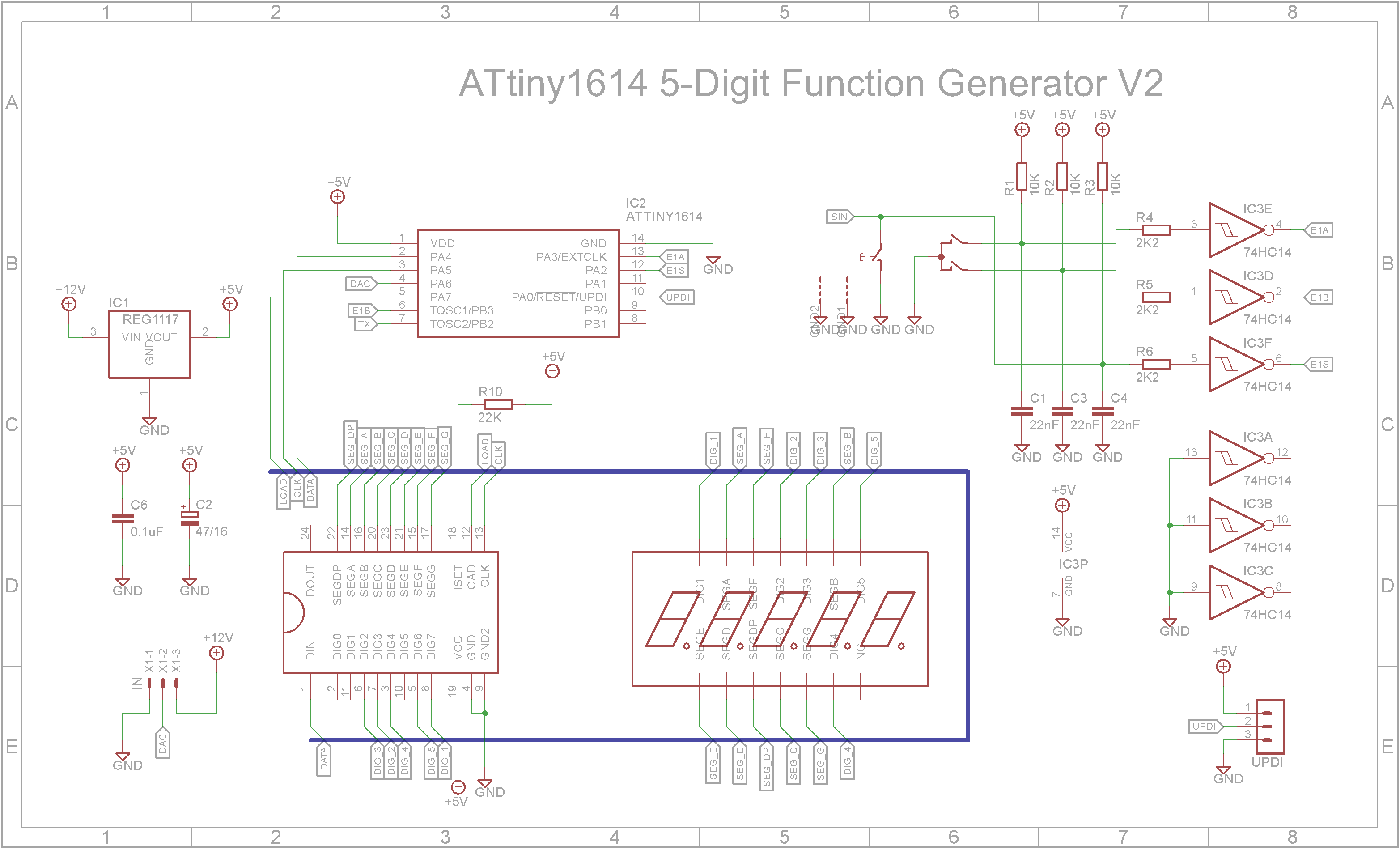
Because the ATtiny1614 processor only comes in SMD packages, I decided to use mostly SMD packages on the oscillator PCB. The user interface is a 5-digit 7-segment display module driven by a MAX7219 LED driver and a rotary encoder. The board also contains a Schmitt Trigger for each rotary encoder contact as well as its push switch. This will de-bounce the mechanical contacts.
I have included the Eagle files in case you want to get the board commercially made or do as I did and make it yourself. I used the Toner method.
Start by adding the SMD components. I find it easier to use solder paste rather than use solder from a reel when soldering SMD components.
Add the links if your board is single sided.
Next add the headers. If your board has through hole plating, you can solder the wires directly to the board rather than use connectors. If you use headers on a single sided board, here is the method I use to add them.
Place header on PCB with longer pin side down, solder pins, push black plastic down towards the PCB.
Next add the display and rotary encoder to the top-side of the board.
Unlike the earlier ATtiny series such as the ATtiny85, the ATtiny1614 uses the RESET pin to program the CPU. To program it you need a UPDI programmer. I made one using a Arduino Nano. You can find complete build instructions at Create Your Own UPDI Programmer. It also contains the instructions for adding the megaTinyCore boards to your IDE.
Once the board has been installed in the IDE, select it from the Tools menu.
Select the ATtiny1614 board in your IDE
Select Board, chip, clock speed, COM port the Arduino Nano is connected and the programmer
The Programmer needs to be set to jtag2updi (megaTinyCore).
Open the sketch and upload it to the ATtiny1614.
Using the oscillator module / function generatorThe function generator has a setup mode and run mode. While in setup mode, no output is generated.
When powering on or pressing the rotary encoder while the oscillator is running, the waveform selection menu is displayed. Use the rotary encoder to go forward or back through the various waveforms. Press the rotary encoder to set the highlighted waveform.
Once you select the waveform, the frequency will be displayed. The most significant digit will start flashing.
Either turn the rotary encoder to change the digit's value or press the rotary encoder to advance to the next digit. Turning the rotary encoder will adjust all digits to the left of the selected digit. For example if the 100s' digit is flashing, turning the rotary encoder to the right, will increase the 100s' digit up pass 900 by automatically adjusting the 1000s' digit for you.
Once the frequency is set to the value you want to output, keep pressing the rotary encoder until the displays stops flashing and any leading zeros are no longer shown. This means the system is in run mode and a 2.5V peak-to-peak signal matching the selected frequency and waveform will appear on the DAC output pin.
The DAC output has a reasonably high impedance. While this is fine for an oscilloscope, it is insufficient to drive low impedance loads such as speakers, etc. Also a typical oscillator when outputting a sine wave usually swings between a positive and negative voltage.
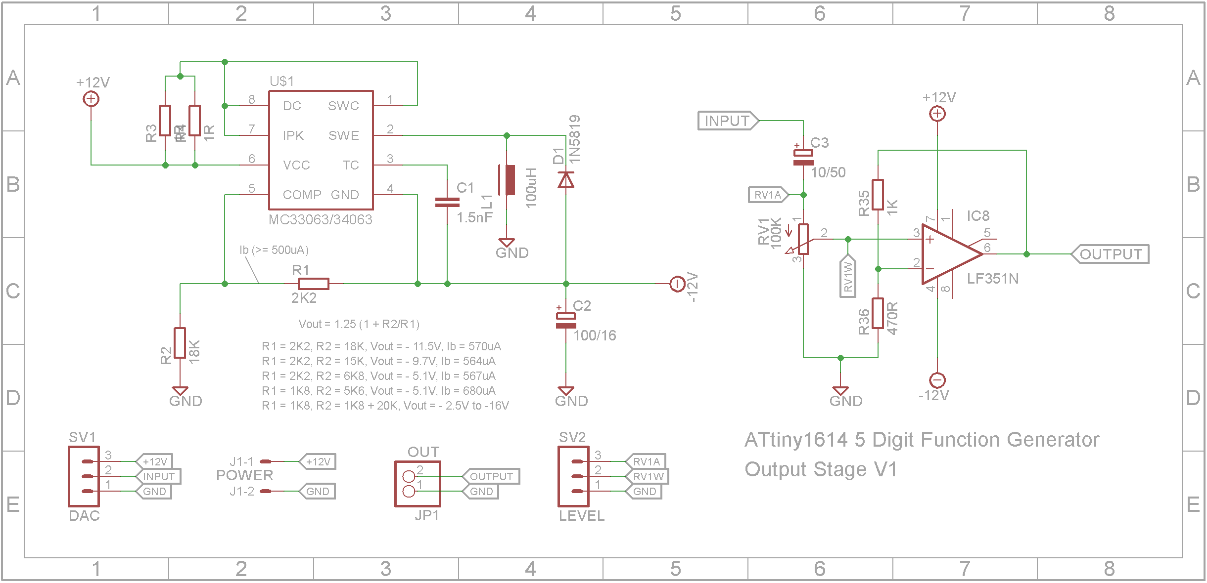
The final oscillator unit is powered from a 12V power brick. I designed a simple board that consists of a -12V generator and a simple Op-Amp buffer and amplifier.
You may need to play with R35 to increase the gain of the output stage. I ended up using a 2K2 ohm resistor to increase the output to around 18V ptp.
Building the caseThe STL files are included. Either take these to a 3D print shop or if you have your own printer, run them through your slicing software. I used a 0.2mm layer height and they need orientating in your slicing software.
On the base, drill out the four PCB mounting holes with a 2.5mm drill and create a thread with a 3mm tap.
The lugs that hold the shells together are a bit fragile. I glued on washers before I drilled the holes with a 2.5mm drill and created a thread with a 3mm tap. Drill out the holes that the screws go through with a 3mm drill.
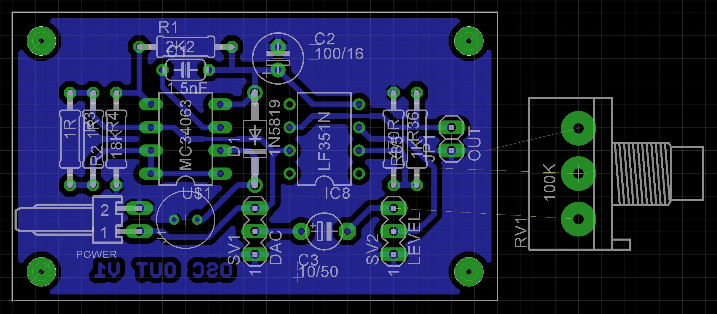
The output board uses through hole components exclusively. I used a polarized header for the power connector and pin headers for the other connectors. Use a dab of red paint on the male pin headers to show which end the red wire goes to as the plugs can go in either way round.
Once tested, screw on the top using 6mm M3 screws.
The waveform can be improved by using a low-pass filter to smooth out the stepped curve outputted by the DAC. However a low-pass filter will have an impact on square waves as it will affect the rise and fall times resulting in a logarithmic rise and fall as the waveform switches from Vmax to Vmin and vice-versa.
Overall it was an interesting build and the DAC in the ATtiny1614 worked as expected.
UpdateI rewrote the while loop in the runOscillator function in assembly language. This reduced the time taken to execute one iteration of the while loop from 57 CPU cycles to 17 CPU cycles. You can see the impact this has made on the quality of the output signal as the frequency is increased.
You can find the updated AudioOscillatorV4.ino code file in the attachments section of my How to embed assembly language into a C program tutorial.


Comments
Please log in or sign up to comment.