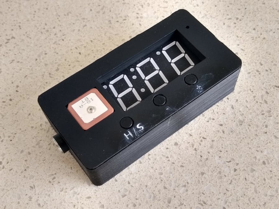
This project is a rebuild of Car HUD - Windscreen Display for Speed & Compass by marcozonca. I really liked the concept. Having a number of 0.8in 4-Digit 7 Segment displays left over from my WeMos Flower Alarm Clock build (I could only buy the displays in lots of 5), this seemed like a good project to use one on. The completed unit measures 97x50x25mm.
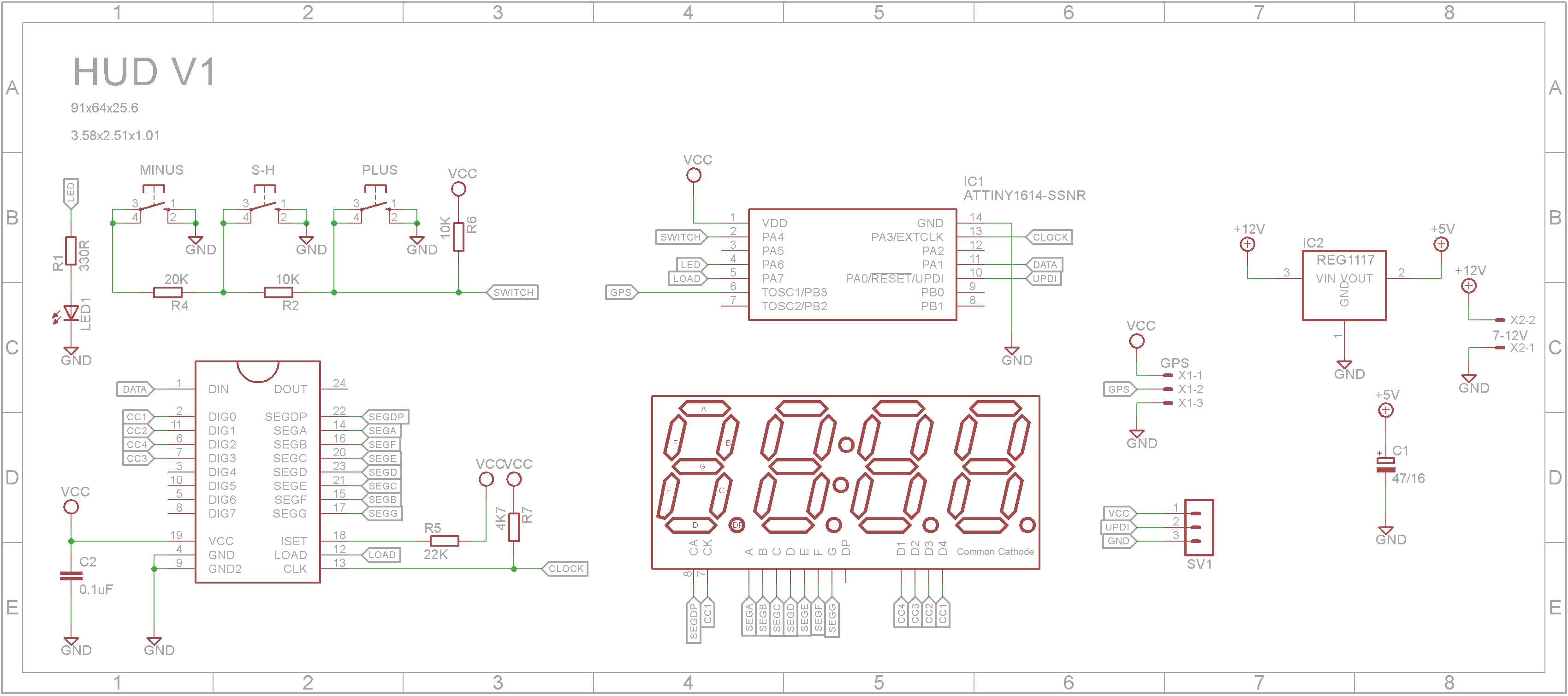
Hardware designTo reduce the size of the finished unit, I decided to redesign the circuit to use a MAX7219 display driver and a ATtiny1614 microprocessor. The switches form a voltage divider and are connected to a single pin as a analog signal. Although the 7 segment display contains four digits, only three are used and the other is covered up by the GPS unit. Since the ATtiny1614 is programmed using a UPDI interface, the GPS is permanently connected to the CPU's RX pin.
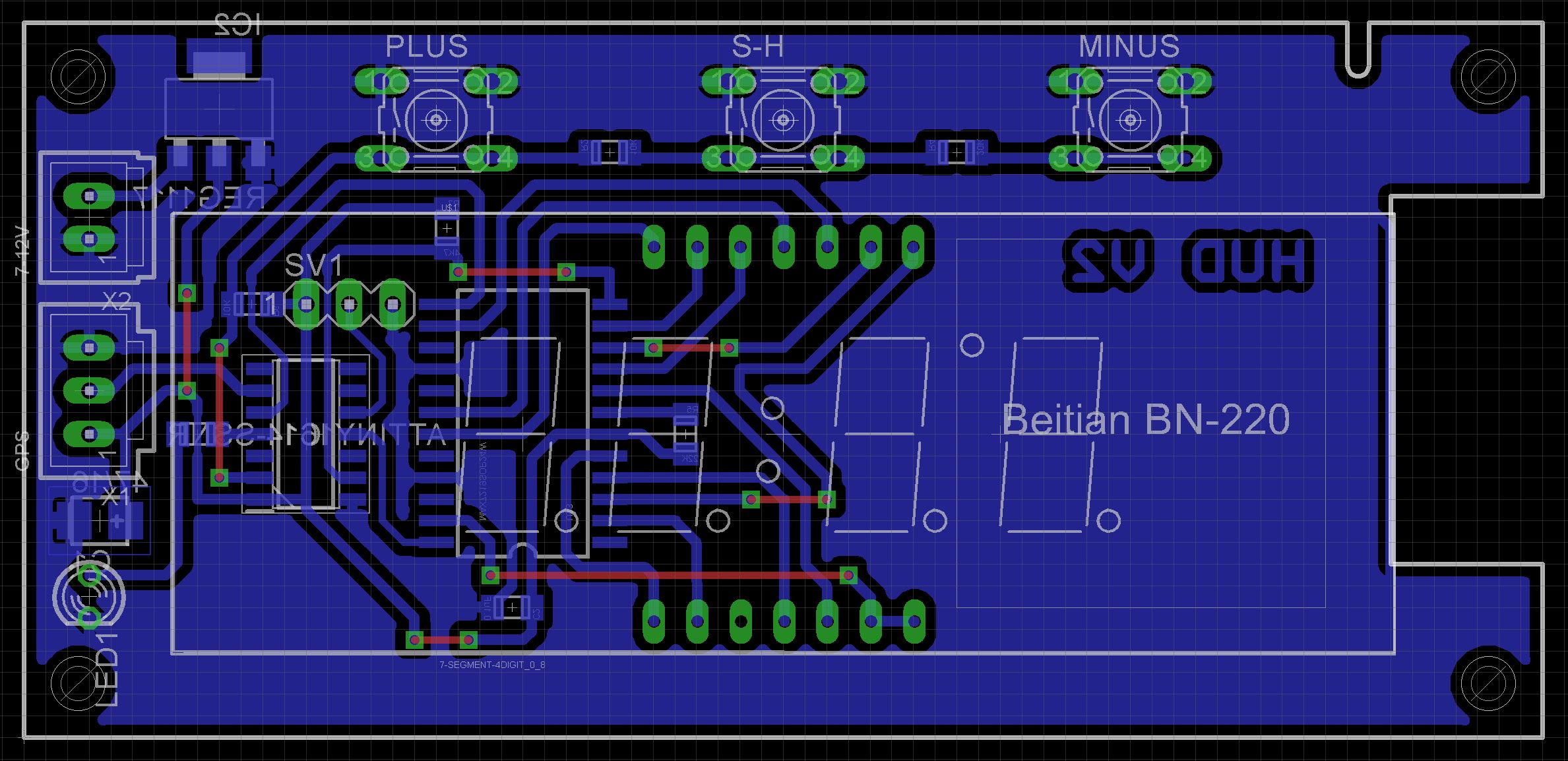
Surface mount components have been used to reduce the board size. To simplify the routing, the digit pins on the display are not mapped to their corresponding pins on the MAX7219 driver IC. The software makes allowances for this and adjusts the output accordingly. The Eagle Files have been included should you wish to get the board commercially made or you can make it yourself. I used the Toner method to make mine.
The STL files are included. Either take these to a 3D print shop or if you have your own printer, run them through your slicing software. I used a 0.2mm layer height with no supports.
On the front panel, drill out the four PCB mounting holes with a 2.5mm drill and create a thread with a 3mm tap.
Make sure the top fits snugly onto the bottom. You might need to do some filing if it is too tight.
Assembly - Step 1Start by adding the SMD components. I find it easier to use solder paste rather than use solder from a reel when soldering SMD components.
Add the links if your board is single sided.
Next add the headers. If your board has through hole plating, you can solder the wires directly to the board rather than use connectors. If you use headers, dab a bit of red paint on the +VE pin since pin headers aren't polarized. This will allow you to know to which end the red wire goes.
Add the display and buttons. Use super glue to glue the button tops to the shaft. Be careful with the glue and don't let it run down the shaft and into the button itself. Do not solder in the 3mm LED yet. Just sit it in place. It will be soldered once the PCB is screwed onto the front panel.
Plug in the cable that came with the GPS and add the GPS unit to the front panel. It should be a snug fit.
Using a 4mm drill bit, counter-sink the back of the hole for the 3mm LED. The purpose of this is to ensure the LED seats itself in the center of its hole but not go right through.
Screw on the PCB using either 6mm or 8mm M3 screws. You can now cut the GPS cable and add a pin header. Red goes to VCC pin, White goes to RX pin, Black goes to GND pin. The green wire is not used.
Push the LED hard up against the front panel. Having the hole counter-sunk will make it easier to find the hole's center. Once in place, solder it to the board and cut away any excess wire.
Screw the DC panel socket to the box. Using some pliers, bend the pins at right angles. The longer pin is negative and the shorter pin is positive. Wire it up to the PCB either directly or use a 2-pin female pin header. Test you have the polarity correct BEFORE you connect the power to the PCB.
The ATtiny1614 is part of the new breed of ATtiny microprocessors. Unlike the earlier series such as the ATtiny85, the new breed use the RESET pin to program the CPU. To program it you need a UPDI programmer. I made one using a Arduino Nano. You can find complete build instructions at Create Your Own UPDI Programmer. It also contains the instructions for adding the megaTinyCore boards to your IDE.
Once the board has been installed in the IDE, select it from the Tools menu.
Select Board, chip, clock speed, COM port the Arduino Nano is connected and the programmer
The Programmer needs to be set to jtag2updi (megaTinyCore).
Open the sketch and upload it to the ATtiny1614.
Software changesUsing a MAX7219 means that the software can use the standard Arduino LedControl library. This simplifies the code considerably. I have removed a lot of the unused code and rewrote the string parser.
Sketch stats are:
Sketch uses 9708 bytes (59%) of program storage space. Maximum is 16384 bytes.
Global variables use 316 bytes (15%) of dynamic memory, leaving 1732 bytes for local variables. Maximum is 2048 bytes.
ConclusionThanks marcozonca for a delightful project. It amazes me just how cheap some of these modules have become. Who would of thought even a few years ago that you could get a complete GPS unit for under $10.


_1x_bGT19vVAby.png?auto=compress%2Cformat&w=40&h=40&fit=fillmax&bg=fff&dpr=2)


Comments
Please log in or sign up to comment.