


Hardware components | ||||||
| × | 1 | ||||
 |
| × | 1 | |||
 |
| × | 1 | |||
| × | 1 | ||||
 |
| × | 1 | |||
| × | 1 | ||||
Software apps and online services | ||||||
 |
| |||||
Hand tools and fabrication machines | ||||||
 |
| |||||
 |
| |||||
Looking around for something to build, I came across a project called Contact Digital Thermometer With Deep Sleep by Neutrino-1.
After making a breadboard prototype of the original circuit, I found the piezo element, which is used to switch on the unit, unreliable. The other issue I had was that the original design measured once and switched itself off.
Demonstration of the new designPushing the switch will turn on the thermometer. A splash screen is displayed and a 3 second delay allows the DS18B20 temperature sensor to initialize. While the unit is on, the temperature is updated every half second.
To turn the unit off, press the switch again while it is showing the temperature. This will put the unit into a deep sleep mode until the switch is pressed again.
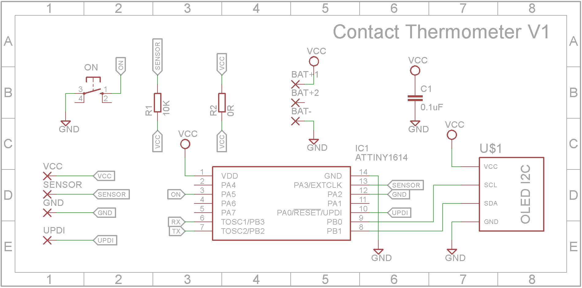
Hardware designThe original version by Neutrino-1 used a ATtiny85. I decided to replace it with a ATtiny1614 microprocessor. This processor has a very low power consumption in sleep mode.
The piezo element is replaced with a 12mmx12mm tactile push switch.
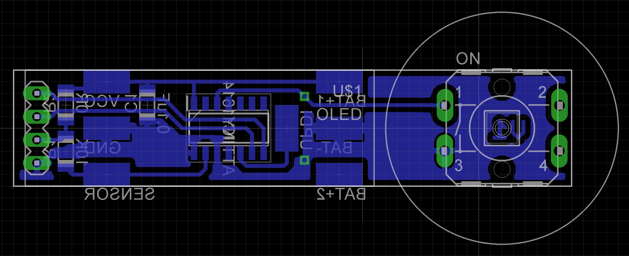
I made a custom PCB to hold the microprocessor and associated connections.
The top part of the case has been modified to allow for the tactile switch.
Building the unitThe case is 3D printed using a 0.1mm layer height. Open the STL files in your slicer software or if you don't have a 3D printer, provide them to your local print shop. You need supports for both the top and bottom parts of the case.
The Eagle files are included in case you want to get the board commercially made or you can make it yourself. I used the Toner method to make mine.
Start by adding the SMD components to the board. I find it easier to use solder paste rather than use solder from a reel when soldering SMD components.
Super glue the battery holder on the copper side of the board. I bent the middle pin (negative pin) so it could be soldered directly onto its pad. The outside pins (positive pins) were connected using tinned copper wire.
The switch is held in place using super glue. Do not solder it on to the PCB as the solder joints will hinder and possibly short out when the battery is inserted. Instead, run two wires from the switch pins to the two holes provided. (see picture below).
The OLED screen will need support. I glued on the plastic part of a 4 pin header after removing the pins.
Next add the OLED display.
The stainless steel waterproof DS18B20 temperature probe needs its heat shrink cover removed. Carefully cut this away leaving the raw wires. Cut and solder the wires to their respective pads.
Unlike the earlier ATtiny series such as the ATtiny85, the ATtiny1614 uses the RESET pin to program the CPU. To program it you need a UPDI programmer. I made one using a Arduino Nano. You can find complete build instructions at Create Your Own UPDI Programmer. It also contains the instructions for adding the megaTinyCore boards to your IDE.
To connect the programmer, tack wires to the UPDI pad, Battery negative pad and Battery positive pad. Once you have programmed the ATtiny1614, these wires can be removed.
Once the board has been installed in the IDE, select it from the Tools menu.
Select the ATtiny1614 board in your IDE
Select Board, Chip, Clock speed, and the COM port that the Arduino Nano is connected to.
The Programmer needs to be set to jtag2updi (megaTinyCore).
Open the sketch and upload it to the ATtiny1614.
Closing the caseThanks Neutrino-1 for a delightful project. I'm not sure that I actually have a use for it but it was a fun build in any event. 👍👍👍


Comments
Please log in or sign up to comment.