A soldering station is designed to regulate the temperature of the tip of a soldering iron enhancing its life-span. Recently I purchased a Hakko 907 clone soldering iron from Ali-Express. It incorporates a heating element and a temperature sensor.
The soldering iron comes with a GX-16 5 Pin female plug.
However what I learn't was that the temperature sensor can either be a thermistor or a thermocouple. Hakko 907 irons come in many varieties.
The element in the 907A is 36 watts and has a K type THERMOCOUPLE sensor, so the station circuit relies on measuring a VOLTAGE in order to determine the element temperature.
The element in the 907F is 50 watts and has a PTC type THERMISTOR sensor, so the station relies on measuring a RESISTANCE in order to determine the element temperature.
907A For YIHUA 936/936B/937D/8786D/898D/878/878A/878D/878AD/8786D
907C For YIHUA 853D 853DA
907I Blue For YIHUA 862BD+/899D+/882D+/892D+/939BD+/862DA+/942
907I Red For YIHUA 995D, 995D+
907F For YIHUA 853D+
907O For YIHUA 853D
907G For YIHUA 8786D I
The one used in this project is the 907A and has a K-Type thermocouple as its temperature sensor.
A thermocouple is a device that consists of two different electrical conductors that form an electrical junction—thermal junction. The change in temperature at the junction creates a slightly but measurable voltage at the reference junction that can be used to calculate the temperature.
A thermocouple can be made of different metals. The metals used will affect the voltage range, cost, and sensitivity. There are standardized metal combinations that result in different thermocouple types: B, E, J, N, K, R, T, and S.
MAX6675 ICThe MAX6675 is a Cold-Junction-Compensated K-Thermocouple to Digital Converter IC. By using this integrated circuit, the code is simplified as it doesn't require any configuration.
My soldering station is a W.E.R 853D. It contains a hot air gun, temperature controlled soldering iron and a power supply. The soldering iron section is simple to use so I decided to duplicate the design. It has a 3-Digit 7-Segment display and two buttons to control the temperature.
I wanted to design the case to fit under the soldering iron holder so the power switch is on the back of the unit to allow the GX-16 5-Pin male socket to be on the front panel.
The heater element in the iron requires a 24V power supply. I purchased a 4 Amp supply from Ali-Express.
Also from Ali-Express is the power socket that incorporates a fuse and power switch.
The case is designed to incorporate the soldering iron stand and the up to 10 soldering iron tips.
All 3D printing is done using a 0.2mm layer height. You will need to rotate the parts in your slicer software so they will sit flat on the build plate. Supports only required for "SS - Top.stl".
When printing "SS-Text.stl", switch to a contrasting color at the start of layer 4. Use double-sided tape or glue to join "SS - Text.stl" to "SS - Front.stl".
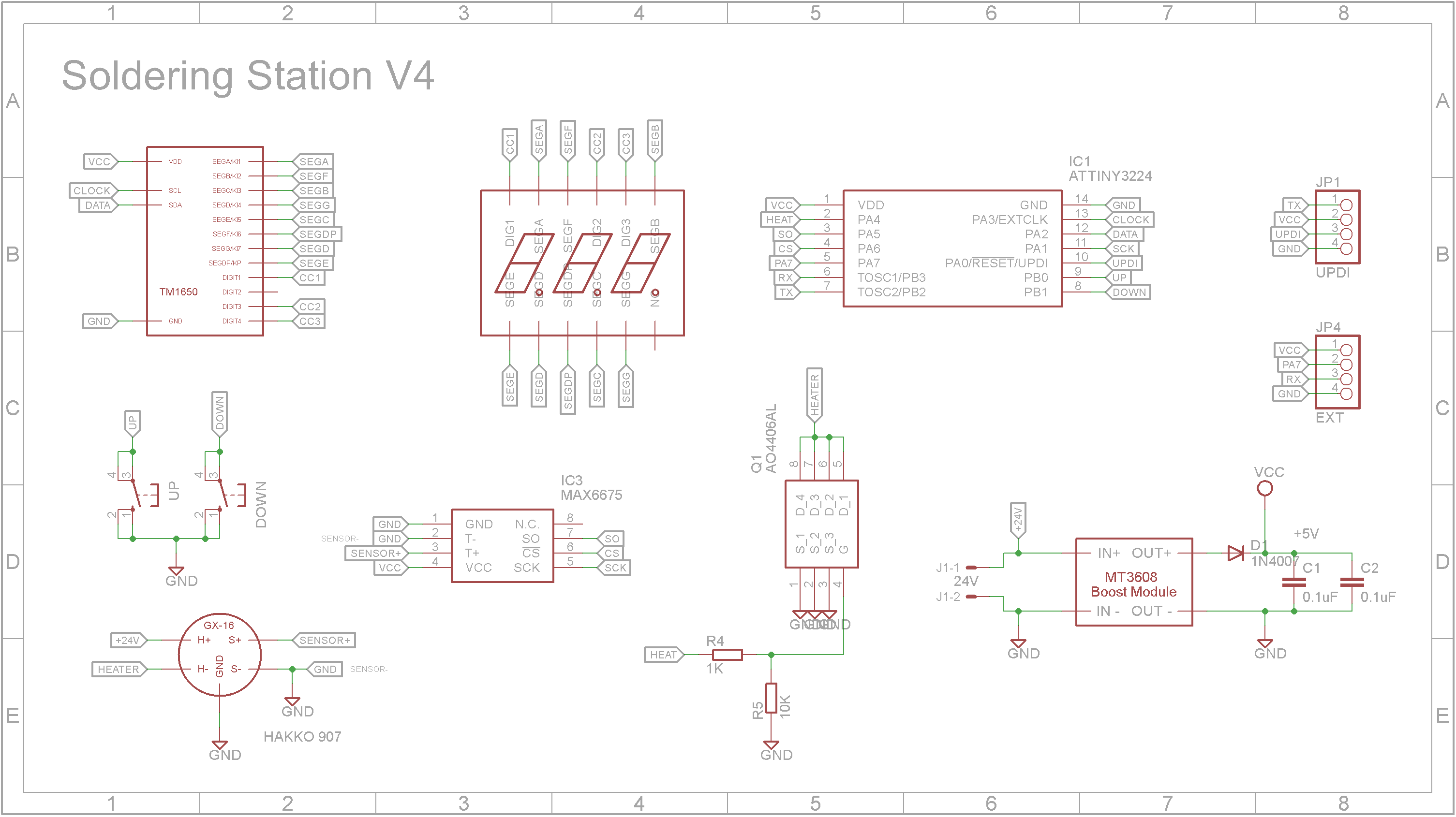
SchematicThe 3-Digit 7-Segment CC display is driven by a TM1650 driver IC. The thermocouple in the iron is read by the MAX6675 K-Thermocouple to Digital Converter IC. The heater in the iron is controlled using PWM generated by the ATtiny3224 microprocessor. It switches the heater on and off via a AO4406 N-Channel MOSFET. The 5V supply is handled by a small regulator board and is taken from the 24V supply that powers the heater element.
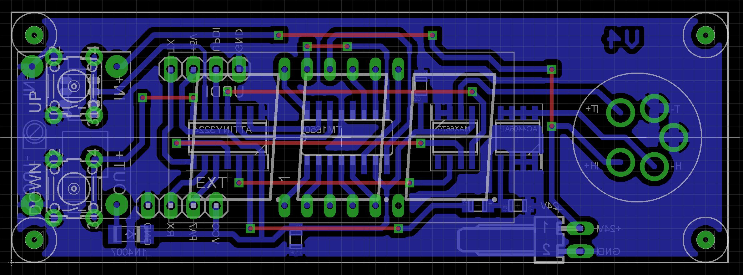
The PCB is designed to be screwed onto the front of the case. This eliminates the need to separately wire the GX-16 Socket, switches and display to the PCB. The Eagle files have been included should you wish to have the board commercially made or you can do as I did and make it yourself. I used the Toner method.
Start by adding the SMD components. I find it easier to use solder paste rather than use solder from a reel when soldering SMD components. I used my SMD Hot Plate to reflow the solder paste.
Add the links if your board is single sided.
Add the two 4 pin headers and the KF2510 2 pin male right angle connector to the copper side of the PCB. Also add four single pin headers for the regulator module.
3D print "SS - Spacers.stl" and glue the spacers to the 3-Digit display
Solder on the display and the two 14mm 6x6 tactile switches.
Glue the button tops to the switches using super glue. Ensure that the glue doesn't drip down the shaft and into the switch.
Seat (don't solder yet) the GX-16 male 5-Pin socket and screw on the board to the front panel using four M2 4mm screws.
Push the GX-16 socket hard against the front panel and solder the pins to the PCB.
Set the regulator module to 5.6V before soldering it to the pins on the PCB.
Screw the 24V power supply to the bottom of the case using four M4 6mm screws.
Screw on the power socket on the back panel and wire to 24V power supply board. When using barrier terminal connectors with high voltages or high currents, I strongly recommend using Ferrules when screwing in the cables. (See TO FERRULE OR NOT TO FERRULE).
You can leave off the mono 3.5mm socket. It maybe used for a future enhancement to detect when the iron is in it's holder.
Unlike the earlier ATtiny series such as the ATtiny85, the ATtiny1614 uses the RESET pin to program the CPU. To program it you need a UPDI programmer. I made one using a Arduino Nano. You can find complete build instructions at Create Your Own UPDI Programmer. It also contains the instructions for adding the megaTinyCore boards to your IDE.
Once the board has been installed in the IDE, select it from the Tools menu.
Select the ATtiny3224 board in your IDE
Select Board, chip, clock speed, COM port the Arduino Nano is connected and the programmer
The Programmer needs to be set to jtag2updi (megaTinyCore).
Open the sketch and upload it to the ATtiny3224.
Note: Do not plug in the unit while the UPDI programmer is connected.
ConclusionThe unit works as designed and will help improve the life-span of your soldering iron.
A future improvement would be to reduce the temperature when the iron is not used but still hot enough to heat up to temperature in a few seconds as soon as the iron is moved. Unfortunately the iron handle doesn't have a vibration sensor so detecting whether the iron is not being used would need some type of sensor on the soldering iron holder. Maybe some type of inductive loop or micro switch
¯\_(ツ)_/¯


Comments
Please log in or sign up to comment.